Pulse-jet Cleaning system

bag filter dust collector supplier Philippines

Pulse-jet Cleaning system

Posted on

Best Pulse-jet Cleaning system of bag filter dust collector supplier Philippines

Bag filter dust collector supplier Philippines understands the facts that advantage of pulse-jet cleaning compared to shaker or reverse-air baghouses is the reduction in baghouse size (and capital cost) allowed by using less fabric because of higher gas-to-cloth ratios and, in some cases, by not having to build an extra compartment for off-line cleaning. However, the higher gas-to-cloth ratios cause higher pressure drops that increase operating costs. This form of cleaning uses compressed air to force a burst of air down through the bag and expand it violently. As with shaker baghouses, the fabric reaches its extension limit and the dust separates from the bag. Air escaping through the bag carries the separated dust away from the fabric surface. In pulse jets, however, filtering gas flows are opposite in direction when compared with shaker or reverse-air baghouses.

Caged Filters used by bag filter dust collector supplier Philippines

In conventional pulse-jet baghouses, bags are mounted on wire cages to prevent collapse while the dusty gas flows from outside the bag to the inside during filtration. Instead of attaching both ends of the bag to the baghouse structure, the bag and cage assembly generally is attached only at the top. The bottom end of the assembly tends to move in the turbulent gas flow during filtration and may rub other bags, which accelerates wear.

Often, bag filter dust collector supplier Philippines are not compartmented. Bags are cleaned one row at a time when a timer initiates the burst of cleaning air through a quick-opening valve. A pipe across each row of bags carries the compressed air. The pipe has a nozzle above each bag so that cleaning air exits directly into the bag. Some systems direct the air through a short venturi that is intended to entrain additional cleaning air. The pulse opposes and interrupts forward gas flow for only a few tenths of a second. However, the quick resumption of forward flow redeposits most of the dust back on the clean bag or on adjacent bags. This action has the disadvantage of inhibiting dust from dropping into the hopper, but the advantage of quickly reforming the dust cake that provides efficient particle collection.

To increase filter area in the same volume of baghouse, star-shaped and pleated (in cross section) bag/cage configurations have been developed. The bag/cage combination is designed as a unit to be installed similarly to a standard bag and cage unit. Such units can be used as replacements by bag filter dust collector supplier Philippines for standard bags and cages when additional fabric area is needed, or may be used in original designs. Normal pulse cleaning is used, i.e., no special changes to the cleaning equipment are required. Costs for star-shaped bags and cages are about three to three and-a-half times normal bags and cages.

Cartridge Filters used by bag filter dust collector supplier Philippines

Further increases in filter area per unit of baghouse volume are obtained by using finely pleated filter media supported on a wire framework. This cartridge can be mounted vertically as a nearly direct replacement for standard bags and cages in existing baghouses, or mounted horizontally in original designs. When used as a direct replacement for standard bags and cages, retrofit costs for one case are 70 % of the cost of building a new baghouse. Cleaning of early cartridge baghouse designs is by typical pulse equipment using a blow pipe across a row of cartridges. More recent designs use individual air valves for each pair of cartridges.

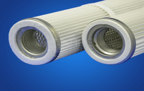
One type of cartridge contains an inner supporting core surrounded by the pleated filter medium and outer supporting mesh. One end of the cartridge is open, which allows gas passing through the filter from the outside to exit to a clean air plenum. Cleaning air is pulsed through the same open end, but in a reverse direction from the gas being cleaned. The other end of the cartridge is closed by an end cap. The manufacturing process followed by bag filter dust collector supplier Philippines requires strong, rigid joints where the end caps attach to the filter medium and cores. Epoxy or polyurethane plastics are used to seal the medium against the end caps. The cartridge is held tightly in place against a mounting plate surrounding the hole that connects it to the clean air plenum. Horizontal cartridges are typically mounted in tandem with a gasket seal between them. If not properly mounted or if the gasket material is not of high quality, leakage will occur after repeated cleaning pulses.

Filter media for cartridges may be paper, spunbonded monofilament plastics (polyester is predominant), or nonwoven fabrics. Cartridges may be from 6 in. to 14 in. in diameter and 16 in. to 36 in. in length. The filtering surface is from about 25 ft2  to 50 ft2  for cartridges with nonwoven fabrics, about three to four times as much with spun bondeds, and more than six times as much with paper. A typical cartridge of bag filter dust collector supplier Philippines may have 36 ft2 of nonwoven fabric, 153 ft2 of spunbonded fabric, or 225 ft2 of paper. Pleat spacing is important for two reasons: closer spacing increases filter area for a specific cartridge volume, but closer spacing increases the likelihood of dust permanently bridging the bottoms of the pleats and reducing available filtering area. For non-agglomerating dusts of small particle size, (up to a few micrometers) and benign characteristics for paper, the cartridge may have 12 pleats/in. to 16 pleats/in. Nonwovens under more difficult conditions may have 4 pleats/in. to 8 pleats/in. Pleat depth is 1 in. to 3 in. Pleat arrangement and available volume of cleaning air determine the cleanability of the media for a specific dust. An advantage of paper media is their ability to collect particles less than 2.5 µm in diameter with high efficiency. Overall efficiency can be 99.999+ percent for bag filter dust collector supplier Philippines. Nonwoven media may be an order of magnitude less efficient. However, even glass fiber bags in reverse-air baghouses on combustion sources can collect 2.5 µm particles with 99.9 percent efficiency.

Cartridge filters are limited in temperature by the adhesives that seal the media to the end caps. Operating temperatures of 200 deg F are common, with temperature capability to 350 deg F soon to be marketed.

bag filter dust collector supplier Philippines
Sewage Treatment, Wet Scrubbers, dust collectors and boilers

Wet scrubber – Liquid Storage and Delivery System

Wet scrubber manufactures Philippines

Wet scrubber – Liquid Storage and Delivery System

Posted on

Wet scrubber manufactures Philippines & their Liquid Storage and Delivery System

The liquid storage and delivery system design of Wet scrubber manufactures Philippines consist of a recirculation tank, pump, filters, valves, piping, pressure gauges, and flow meters. Most systems are designed as recycle systems, meaning the spent scrubbing liquid is recirculated through the scrubber system. Since the scrubbing liquid is recycled, the solids content of the liquid increases as PM is collected. The concentration of solids in a recycle system must be maintained below a design limit or the spray characteristics of the system cannot be maintained. To reduce the solids concentration, a portion of the liquid is bled from the system and fresh scrubbing liquid is added. The volume of “make up” liquid also includes the volume of water that is lost due to evaporation by hot waste gas.

Wet scrubber manufactures Philippines takes care that the tank must be sized to provide continuous operation and minimize frequent changing of the liquid. A sensor in the tank monitors the level of liquid. An automated system for adding liquid can be incorporated into the scrubber design. However, oversizing the tank and automating the addition of make-up water increases the capital cost and complexity of the system. The increase in capital cost must be weighed with the O&M cost for operating the liquid storage and delivery system manually.

Solids can be removed from the scrubbing liquid using several different methods. In one method, the scrubbing liquid is gravity fed to a set of filters located upstream of the pump to remove solids. The filter is generally constructed out of stainless steel and is removable for cleaning and replacement. A backup filter and set of isolation valves are often included in the system to facilitate cleaning of the filters while operating the system. Other solids removal methods include liquid cyclones or settling tanks.

After leaving the tank, the scrubbing liquid flows to a pump to increase the pressure and flow rate to the values required for proper operation of the venturi system. Pressure gauges and flow meters downstream of the pump monitor the scrubbing liquid flow and pump operation. Wet scrubber manufactures Philippines generally adds a feedback control system to the system to automate control of the pump.

Wet scrubber manufactures Philippines and their Liquid Injection System

The injection system design promotes mixing of the waste gas and scrubbing liquid in the venturi. There are two basic systems for injecting scrubbing liquid into a venturi system: open pipe (also referred to as “wet approach”) and spray nozzles. The injection systems are generally located in the waste gas duct, directly upstream of the venturi throat section. In both systems, the liquid is injected in the same direction as the waste gas stream. Most injection systems are constructed out of stainless steel or other non-corrosive material.

In an open pipe system, several small diameter pipes feed the scrubbing liquid into the duct section. The pipes inject the liquid tangentially, along the duct walls or radially against baffle plates. The water flows downward, covering the walls of the duct. The piping system is designed by Wet scrubber manufactures Philippines are so that the entire surface area of the section is flooded with the scrubbing liquid. This ensures that there is no dry/wet transitional zone. Dry/wet areas lead to a build-up of solids on the duct wall that interferes with the operation of the scrubber. The dust laden gas enters the scrubber vertically from the top and immediately hits the film of scrubbing water. Some separation of the PM from the waste gas takes place in this area. In the throat section, the waste gas stream becomes very turbulent and the scrubbing liquid is sheared to form a dispersion of droplets. Open pipe systems have lower capital and O&M costs than spray nozzles due to their simpler design.

Spray nozzles systems are sometimes referred to as “jet venturis”or “eductor venturis”. These systems inject liquid through nozzles to create a fine droplet spray pattern. The droplets can be produced either pneumatically or hydraulically using specially designed nozzles heads. While spray nozzles improve mixing between the scrubbing liquid and the waste gas, they generally have higher capital and operating costs than open pipe systems due to the higher pump horsepower required for this type of system.

In jet venturis, the nozzles can be attached to the wall of the duct or can be located in the duct cross section. For throat areas greater than 1 foot in width, a spray nozzle must be located in the center of the duct to ensure adequate liquid-PM contact. Nozzles can be constructed out of stainless steel or more specialized materials such as stellite and ceramic. Because nozzles are prone to plugging and abrasion in high PM load conditions, this type of system requires clean liquid feed to avoid clogging as per wet scrubber manufactures Philippines. High temperatures and gas velocities can damage the nozzles, consequently, they should be designed to be removable for cleaning and replacement.

Wet scrubber manufactures Philippines
Sewage Treatment, Wet Scrubbers, dust collectors and boilers

Avlon Cyclone Separator- Operating Instructions

Industrial dust collector machine

Avlon Cyclone Separator- Operating Instructions

Posted on

Industrial dust collector machine – Avlon Cyclone Separator- Operating Instructions

Avlon Inc, has prepared your new Industrial dust collector machine for shipment in accordance with the Uniform Freight Classification. It has been thoroughly inspected at the factory and, barring damage in transit, should be in excellent condition upon arrival.

The Avlon Inc, Industrial dust collector machine and accessory equipment should be inspected upon receipt for any shipping damage. If dampers or shutters are provided, check these accessories for free operation of all moving parts. When a carrier signs the Avlon Inc, bill of lading, the carrier accepts the responsibility for any subsequent shortages or damage, evident or concealed, and any claim must be made against the carrier by the purchaser. Evident shortage or damage should be noted on the carrier’s delivery document before signature of acceptance. Inspection by the carrier of damage, evident or concealed, must be requested. After inspection, issue a purchase order for necessary parts or arrange for return of the equipment to Avlon Inc, for repair.

Industrial dust collector machine Handling and Storage

Avlon Inc, industrial dust collector machine are shipped completely assembled and skidded when size permits. These units may be handled and moved using good rigging techniques, being careful to avoid concentrated stresses that will distort any of the parts. Items or parts of the industrial dust collector machine that are shipped separately (knocked down) will be clearly labeled for reassembly.

If the cyclone is not to be installed promptly, store it in a clean, dry location to prevent rust and corrosion of steel components. If outdoor storage is necessary, protection should be provided. Cover the inlets and outlets to prevent the accumulation of dirt and moisture inside the housing. Refer to the cyclone maintenance section of this manual regarding any further storage instructions.

Industrial dust collector machine Installation

To ensure appropriate cyclone operation, the unit must be adequately supported and properly installed. After unpacking and inspection has been completed, install the Cyclone with the following guidelines:

The Cyclone has locations where the equipment necessary for lifting the device can be attached. These will be the lifting lugs and/or the frame mounts of the cyclone where it will be attached to a support structure.

Lifting the cyclone at any other point is hazardous and may compromise human safety as well as the structural integrity of cyclone itself.

The cyclone must be lifted by a means with sufficient lifting capacity.

CAUTION: Use the proper equipment when lifting or moving the Cyclone. Make sure all persons and obstructions are clear from path and installation area.

Avlon Inc, Industrial dust collector machine may be supported in two different ways. Smaller industrial dust collector machine may be designed to be supported by the duct work or machinery connected to them, but most are designed with frame mounts in order to be supported by an additional structure or framework. The unit should only be mounted on a structure designed to support it. The cyclone must be separately grounded, and installed on steel construction intended for this purpose. Product inlet or outlet transitions are not designed to support the weight of accessory equipment such as an airlock valve. If the unit is installed outdoors, cross bracing from the angle iron frame may be required for wind loading connections. The Cyclone should be installed in a level position, to prevent material from flowing to one side of the unit, thereby ensuring proper and efficient operation. Remove all foreign material before fully enclosing and operating the cyclone.

Place a bead of caulking (or any provided gasket material) to seal the inlet and outlet points of the cyclone during installation. Proper installation of the cyclone also includes assembling the duct work and required machinery to the cyclone, fully enclosing it for quality operation. The unit should only be operated once it is properly connected and fully encapsulated. All duct work or stacks should be independently supported as excess weight may distort the cyclone assembly, causing improper airflow which may affect the efficiency of the unit, and all subsequent points in the system.

Mounting Points

Lifting Lugs

NOTE: To ensure proper operation and optimum cyclone efficiency, inlet and outlet ductwork design is critical. The ductwork should have a length of straight section from the inlet and outlet of the cyclone that is at least five times the diameter of the duct. If this not possible, elbows in the ductwork should be oriented in a manner that refrains from countering the air rotation inside the cyclone. This will help maintain efficiency. Some acceptable examples include:

General Operating Information

The Avlon Inc, Cyclone classifies dry particles on the basis of terminal velocity. It can make precise separations of particles having differences in terminal velocities. A particle having a lower terminal velocity will be picked up by air moving at a lower velocity than will a particle having a higher terminal velocity As the airflow is increased, particles having higher and higher terminal velocities are removed. The system should be designed with sufficient fan capacity so that the operator is able to remove more material than required. Fine-tuning the system can be accomplished by adjusting the airflow by use of a damper to that which corresponds to or exceeds the terminal velocity of all of the particles that are desired to be removed from the product stream.

Since the terminal velocity of a particle is influenced by, not only the size of the particle, but also its shape and density, there are instances where small dense particles are lifted at the same airflow as large winged particles. Separation of these particles that have the same terminal velocity, but different size and shape, can be improved by Avlon Inc, Multi-Aspiration system, or by sifting (screening). The flow and arrangement of the equipment must be determined by the operator for each product and for each system on an individual basis.

Industrial dust collector machine – Avlon Cyclone Separator- Operating Instructions Avlon Inc, has prepared your new Industrial dust collector machine for shipment in accordance with the Uniform Freight Classification. It has been thoroughly inspected at the factory and, barring damage in transit, should be in excellent condition upon arrival. The Avlon Inc, Industrial dust collector machine and accessory equipment should be inspected upon receipt for any shipping damage. If dampers or shutters are provided, check these accessories for free operation of all moving parts. When a carrier signs the Avlon Inc, bill of lading, the carrier accepts the responsibility for any subsequent shortages or damage, evident or concealed, and any claim must be made against the carrier by the purchaser. Evident shortage or damage should be noted on the carrier’s delivery document before signature of acceptance. Inspection by the carrier of damage, evident or concealed, must be requested. After inspection, issue a purchase order for necessary parts or arrange for return of the equipment to Avlon Inc, for repair. Industrial dust collector machine Handling and Storage Avlon Inc, industrial dust collector machine are shipped completely assembled and skidded when size permits. These units may be handled and moved using good rigging techniques, being careful to avoid concentrated stresses that will distort any of the parts. Items or parts of the industrial dust collector machine that are shipped separately (knocked down) will be clearly labeled for reassembly. If the cyclone is not to be installed promptly, store it in a clean, dry location to prevent rust and corrosion of steel components. If outdoor storage is necessary, protection should be provided. Cover the inlets and outlets to prevent the accumulation of dirt and moisture inside the housing. Refer to the cyclone maintenance section of this manual regarding any further storage instructions. Industrial dust collector machine Installation To ensure appropriate cyclone operation, the unit must be adequately supported and properly installed. After unpacking and inspection has been completed, install the Cyclone with the following guidelines: The Cyclone has locations where the equipment necessary for lifting the device can be attached. These will be the lifting lugs and/or the frame mounts of the cyclone where it will be attached to a support structure. Lifting the cyclone at any other point is hazardous and may compromise human safety as well as the structural integrity of cyclone itself. The cyclone must be lifted by a means with sufficient lifting capacity. CAUTION: Use the proper equipment when lifting or moving the Cyclone. Make sure all persons and obstructions are clear from path and installation area. Avlon Inc, Industrial dust collector machine may be supported in two different ways. Smaller industrial dust collector machine may be designed to be supported by the duct work or machinery connected to them, but most are designed with frame mounts in order to be supported by an additional structure or framework. The unit should only be mounted on a structure designed to support it. The cyclone must be separately grounded, and installed on steel construction intended for this purpose. Product inlet or outlet transitions are not designed to support the weight of accessory equipment such as an airlock valve. If the unit is installed outdoors, cross bracing from the angle iron frame may be required for wind loading connections. The Cyclone should be installed in a level position, to prevent material from flowing to one side of the unit, thereby ensuring proper and efficient operation. Remove all foreign material before fully enclosing and operating the cyclone. Place a bead of caulking (or any provided gasket material) to seal the inlet and outlet points of the cyclone during installation. Proper installation of the cyclone also includes assembling the duct work and required machinery to the cyclone, fully enclosing it for quality operation. The unit should only be operated once it is properly connected and fully encapsulated. All duct work or stacks should be independently supported as excess weight may distort the cyclone assembly, causing improper airflow which may affect the efficiency of the unit, and all subsequent points in the system. Mounting Points Lifting Lugs NOTE: To ensure proper operation and optimum cyclone efficiency, inlet and outlet ductwork design is critical. The ductwork should have a length of straight section from the inlet and outlet of the cyclone that is at least five times the diameter of the duct. If this not possible, elbows in the ductwork should be oriented in a manner that refrains from countering the air rotation inside the cyclone. This will help maintain efficiency. Some acceptable examples include: General Operating Information The Avlon Inc, Cyclone classifies dry particles on the basis of terminal velocity. It can make precise separations of particles having differences in terminal velocities. A particle having a lower terminal velocity will be picked up by air moving at a lower velocity than will a particle having a higher terminal velocity As the airflow is increased, particles having higher and higher terminal velocities are removed. The system should be designed with sufficient fan capacity so that the operator is able to remove more material than required. Fine-tuning the system can be accomplished by adjusting the airflow by use of a damper to that which corresponds to or exceeds the terminal velocity of all of the particles that are desired to be removed from the product stream. Since the terminal velocity of a particle is influenced by, not only the size of the particle, but also its shape and density, there are instances where small dense particles are lifted at the same airflow as large winged particles. Separation of these particles that have the same terminal velocity, but different size and shape, can be improved by Avlon Inc, Multi-Aspiration system, or by sifting (screening). The flow and arrangement of the equipment must be determined by the operator for each product and for each system on an individual basis.
Sewage Treatment, Wet Scrubbers, dust collectors and boilers

Chemicals used by wastewater treatment manufacturers Philippines

wastewater treatment manufacturers Philippines

Chemicals used by wastewater treatment manufacturers Philippines

Posted on

Chemicals used by wastewater treatment manufacturers Philippines

Wastewater treatment manufacturers Philippines uses mainly three main chemicals for Chemical Precipitation of Phosphorus in Wastewater; Aluminum, Ferric iron or Lime. Each has different handling issues. Look for the following in the designs:

Aluminum Sulfate (Alum)

The pH of Alum is 3.0-3.5 so pH control will be needed afterwards.

Corrosive when wet. All storage bins and piping should be constructed with stainless steel, fiberglass-reinforced plastic, PVC or other plastics, or concrete tanks.

Shall be stored and added at temperatures 25 degrees F and above to prevent crystallization.

Works best at wastewater pH of 5.5-6.5.

Sodium Aluminate

Formation of NaOH increases pH. This is a strong caustic and is not corrosive.

Shall be store and used within three months. Dry Aluminate deteriorates with exposure to the atmosphere.

Store in stainless Steel or concrete. Wastewater treatment manufacturers Philippines generally avoid alloys, rubber and aluminum parts.

Ferric Chloride

Has a pH of 2.0 and is very corrosive. Will require pH control.

Corrosive, use steel lined with rubber or plastic or synthetic resin storage tanks.

Wastewater treatment manufacturers Philippines generally stores ferric chloride in heated building or in heated tanks to prevent crystallization.

Pump component should be constructed of graphite or rubber lined pumps with Teflon seals. Metering pumps are typically of the positive displacement type, either diaphragm or plunger.

Piping, use steel lined with Saran, FRP or plastics. Valves should be rubber or resin lined diaphragm valves, Saran lined valves with Teflon diaphragms, rubber sleeved pinch valves or plastic ball valves.

Works best at wastewater pH of 4.5-5.0.

Ferrous Chloride

Corrosive. Same storage, pumping and piping as Ferric Chloride.

Precipitation will not occur until ferrous ion is oxidized to ferric ion.

Works best at wastewater pH of 8.0.

Ferrous Sulfate.

Acidic when dissolved in water.

Phosphorus precipitation does not occur until ferrous ion is oxidized to ferric ion.

Oxidizes and hydrates in moist air. Must be kept in dry area and out of humidity.

Will cake up at storage temperatures greater than 68 F, must be kept cool.

Storage containers may be constructed of concrete, synthetic resin or steel and wastewater treatment manufacturers Philippines gives and additional lined with asphalt, rubber, PVC or chemically resistant resins.

Works best at wastewater temperature of 8.0.

Lime (Calcium Carbonate)

Creates significant increases in sludge up to 2-3 times the normal amount generated.

Must be added till pH is up around 10. This often causes the biological upsets in treatment facilities.

Phosphorus is released under anaerobic conditions. Sludge handling must be addressed.

Polymer – dry or liquid form

Used in conjunction with aluminum and iron salts to assist in flocculation and settling of metal phosphate floc.

Added at least 10 seconds after metal salt addition, preferably 2-5 minutes later.

Dry polymers require mixing and aging before use. Liquid polymers can be used immediately.

Must be stored in cool, low humidity areas. Storage tanks are FRP, type 316 stainless steel, or plastic lined steel tanks.

Do not store polymer for a long time, three days after dry solution is mixed.

BIOLOGICAL PHOSPHORUS REMOVAL

Biological phosphorus removal is carried out by wastewater treatment manufacturers Philippines when wastewater is cycled through alternating anaerobic and aerobic conditions. Wastewater sludge must first pass through an anaerobic condition where bacteria release stored phosphorus. The wastewater then passes through an aerobic phase where bacteria store excess phosphorus in their cells. Design calculations shall show the sludge retention time, the anaerobic contact time and the aerobic detention time.

wastewater treatment manufacturers Philippines
Sewage Treatment, Wet Scrubbers, dust collectors and boilers

CHEMICAL PHOSPHORUS REMOVAL

water treatment suppliers Philippines

CHEMICAL PHOSPHORUS REMOVAL

Posted on

PHOSPHORUS REMOVAL OF WATER TREATMENT SUPPLIERS PHILIPPINES

Phosphorus is present in raw wastewater at typical concentrations of 6-12 mg/l. A typical biological treatment unit will remove at least 2 mg/l of phosphorus. To remove additional phosphorus water treatment suppliers Philippines uses biological phosphorus removal that takes a specific design and closer operator control, or chemical addition. The most common form of chemical addition is a Metal Salt Chemical Addition that forms an insoluble precipitate with orthophosphate. Phosphorus removal efficiencies decrease in cold weather due to decreased settleability of chemical flocs. Chemical addition of metal salts can lower pH levels in the effluent to concentrations below permit limits so pH control may be required. Very low concentrations may also require the addition of polymer to aid in chemical floc settling.

CHEMICAL PHOSPHORUS REMOVAL

If phosphorus concentrations less than 1.0 mg/l are required and metal salt chemical addition is proposed, the following included in the design of a water treatment suppliers Philippines.

  1. Two-point chemical addition – Metal Salts shall be added prior to the primary pretreatment unit and before the final clarifier. The addition of the chemicals shall be flow paced and the chemical shall have adequate a good turbulent mixing zone of at least 30 seconds travel time with the wastewater so a floc can be formed between the chemical and the wastewater.
  2. Polymer Addition – Design for addition of polymer to the wastewater in addition to the metal salt addition to aid in settling of inorganic solids in the clarifiers. Inorganic solids may carry over to the RBC or final sand filter if polymer is not added. water treatment suppliers Philippines understands the facts that inorganic solids going to an RBC will result in a biofilm layer that will interfere with normal treatment.
  3. pH control – Metal Salts will drop the pH in the effluent and bring the facility out of compliance with permit limits.
  4. Effluent polishing – A filter will be required after flocculation and settling to remove remaining suspended solids.
  5. Solids handling – Chemical addition for phosphorus removal can double the amount of sludge handled at the facility. The sludge storage tanks of water treatment suppliers Philippines are sized as large as possible to accommodate the additional sludge. In addition, the clarifiers should have lower loading rates, <600 gpd/sq.ft to aid in the settling of the sludge.
  6. The Suspended Solids concentrations must be 15 mg/l or less. The treatment system should be designed for stricter TSS removal.
  7. Eye Wash and Emergency showers should be located close by. Hand and face protection will be required when handling.
  8. Sludge streams must be treated to prevent removed phosphorus from being released from the sludge. Phosphate release occurs from sludge when there are changes in pH, in the redox condition or in anoxic or anaerobic conditions. Additional storage facilities other than the pretreatment tank will be necessary to prevent phosphorus release.
  9. For facilities using ultraviolet (UV) light for disinfection, the use of iron salts is discouraged as they produce fouling of the quartz jackets. This leads to an accumulation of scale over the wetted surface of the quartz jacket and will impede radiation transmission.
  10. For facilities using aluminum salts, water treatment suppliers Philippines takes special care to insure that their addition will not lead to a violation of effluent standards for aluminum.
water treatment suppliers Philippines
Sewage Treatment, Wet Scrubbers, dust collectors and boilers

Mechanically Cleaned Setting Tanks

wastewater treatment manufacturers

Mechanically Cleaned Setting Tanks

Posted on

Design criteria for Mechanically Cleaned Setting Tanks of wastewater treatment manufacturers

As per wastewater treatment manufacturers the Inlets shall be designed to dissipate the inlet velocity, to distribute the flow equally and to prevent short-circuiting. Channels shall be designed to maintain a velocity of at least one foot per second (30 cm/s) at one-half design flow and to distribute the flow proportionately between parallel units. Corner pockets and dead ends shall be eliminated and corner fillets or channeling shall be used where necessary. Provisions shall be made for easy removal of floating materials in inlet structures having submerged ports.

Scum Baffles – wastewater treatment manufacturers also suggest to provide scum baffles ahead of outlet weirs. Baffles shall be constructed of plate steel or other suitable material.

Weirs – Overflow weirs shall be constructed of plate steel or other suitable material. Weirs shall be properly supported and fully adjustable. Multiple weir troughs shall be placed sufficiently far apart to avoid excessive upward velocity between the troughs.

Protective Devices – All settling tanks shall be designed to provide easy access for maintenance and protection to the operator. Such features shall include stairways, walkways and handrails.

Surface Loading Rates – Surface loading rates for mechanically cleaned setting tanks shall not exceed 600 gallons per day per square foot (24 m3 /m2 d) under average flow conditions nor shall the surface loading rates exceed 3000 gallons per day per square foot (122 m3 /m2 d) under peak conditions as per wastewater treatment manufacturers.

Scum Removal – Provisions shall be made for automatic equipment for scum removal. Provisions shall be made to discharge the scum with the sludge.

Sludge Removal – Removal of sludge from primary settling tanks shall be by direct pump suction. A sludge well shall be provided. All sludge hoppers shall have an individual valved sludge withdrawal line at least 3 inches (7.6 cm) in diameter.

Depth – The liquid depth of mechanically cleaned settling tanks shall not be less than 8.0 feet (2.441.82 m).

Diameter – The diameter of primary settling tanks shall not be less than 8.0 feet (2.4 m) as per wastewater treatment manufacturers guidelines.

Tank Material – Primary settling tanks shall be constructed of reinforced concrete or structural grade steel. Steel tanks shall be adequately protected from corrosion through the use of appropriate coating material. Cathodic protection shall be provided for all buried steel tanks.

Foundation Pad – A poured reinforced concrete foundation pad of sufficient design to withstand the structural load of the settling tank under peak operating conditions shall be provided as per wastewater treatment manufacturers. The foundation pad shall be flat and level. If steel tanks are used, anchoring devices shall be provided to properly secure the settling tank to the foundation pad.

wastewater treatment manufacturers
Sewage Treatment, Wet Scrubbers, dust collectors and boilers

Septic Tank Pre-treatment

septic tank

Septic Tank Pre-treatment

Posted on

What should be the capacity of septic tank?

A septic tank used for pretreatment shall have an effective liquid capacity of not less than 50 percent of the estimated design flow. When garbage grinders are employed or the septic tank is used for sludge storage the effective liquid capacity shall be no less than 75 percent of the estimated design flow. When garbage grinders are employed and the septic tank is utilized for sludge storage, the effective liquid capacity shall be no less than 100 percent of the design flow. Multiple tanks are encouraged for tank sizes greater than 25,000 gallons.

What should be the Liquid Depth of Septic tank?

The liquid depth of the septic tank shall be a minimum of 4 feet. The septic tank may be rectangular, or square in plan, provided the distance between the outlet and the inlet of the tank is at least equal to the liquid depth of the tank.

How many compartments should be there?

Multi-compartment tanks with transverse baffles may be used for pretreatment.  Septic pretreatment tanks may be installed in parallel provided the sewage flow is properly divided such that each tank receives an equal proportion of the total flow.

What are the construction features?

Septic pretreatment tanks shall be watertight (type WT) and shall be constructed of reinforced concrete. Tanks and covers shall be designed and constructed so as to withstand an H-20 wheel load. Any tank installed in a location where there is high ground water shall be weighted to prevent the tank from floating when emptied. Buoyancy calculations shall be included on the design plans for any tank with any portion installed below the anticipated high groundwater elevation.

What should be the MOC and depth of Tees?

Inlet and outlet tees shall be of cast-iron, SDR – 35 PVC, or cast-in-place concrete, and shall extend a minimum of 6 inches above the flow line of the septic tank and be on the centerline of the septic tank located directly beneath the clean out manhole. Any piping extending beyond 6 inches (15 cm) from a tank wall shall be properly supported. There shall be an air space of at least 3 inches (7.62 cm) between the tops of the tees and the inside of the tank cover, and the tops of the tees shall be left open to provide ventilation.

Depth of Tees – The inlet tee (baffles are not acceptable) shall extend a minimum of 12 inches (30 cm) below the flow line. The outlet shall be provided with a tee extending below the flow line in accordance with the following table:

Depth of Outlet Tee

Liquid Depth in Tank                                    Below Flow Line

4 feet                                                               14 inches

5 feet                                                               19 inches

6 feet                                                               24 inches

7 feet                                                               29 inches

8 feet                                                               34 inches

9 feet                                                               39 inches

10 feet                                                             44 inches


What are the other construction details?

Base – Septic tanks shall be installed on a level stable base that will not settle.

Materials – Septic tanks may be constructed of poured reinforced concrete or precast reinforced concrete.

Access Manholes – Septic tanks used for pretreatment shall be provided with at least two 24-inch (61 cm) diameter manholes (over inlet and outlet tees) with metal frames and covers at finished grade. Manhole covers shall be labeled and the type shall be specified in the specifications. Distance between access manholes shall not exceed 15 feet (4.57 m) on center.

Accessibility – Septic tanks shall be located so as to be accessible for servicing and cleaning

Invert Elevation –The invert elevation of the inlet of a septic tank shall be at least 2 inches (5.1 cm) above the invert elevation of the outlet.

Backfill – Backfill around the septic tank shall be placed in such a manner as to prevent damage to the tank and piping.

Groundwater – The invert elevation of the septic tank outlet shall be at least one foot above the maximum ground water elevation. In the case of segmented tanks all joints shall be at least one foot above the maximum ground water elevation.

septic tank
Sewage Treatment, Wet Scrubbers, dust collectors and boilers

RAW SEWAGE PUMPING STATIONS

wastewater treatment suppliers

RAW SEWAGE PUMPING STATIONS

Posted on

RAW SEWAGE PUMPING STATIONS OF WASTEWATER TREATMENT SUPPLIERS

If you browse through the list of wastewater treatment suppliers in Philippines, the sewage pumping stations are used by them only where necessary. Pumping stations shall be protected from physical damage and remain fully operational during a 100-year frequency flood. Wherever possible, pump stations for small-scale installation shall be constructed without a superstructure. Pumping stations shall be readily accessible during all weather conditions.

wastewater treatment suppliers criteria of pumps ?

Submersible pumps shall be used whenever possible. Manholes over pumps shall be of a size that will permit removal of pumps via slide-rails without entering the pump chamber. Minimum access diameter of 24 inches (61 cm) shall be provided. Wet wells shall be vented to the atmosphere by means of a vent pipe, extending not less than 15 feet (4.57 m) above the finish grade, attached to a utility pole, or adjacent building, or other appropriate structure. Centrifugal, suction head pumps are allowed provided the pump station consists of separate wet and dry well.

What shall be the Capacity?

The working capacity (between pump-on and pump-off) should provide a holding period not to exceed 10 minutes for the average daily design flow. All pump stations shall have an emergency storage capacity (above the working level) of 6 hours without overflowing or causing backups.

What is the Pump Type?

Submersible pumps shall be designed specifically for submerged use in raw sewage. An effective method to detect shaft seal failure or potential seal failure shall be provided. Pumps shall be capable of passing spheres of at least 3 inches (7.62 cm) in diameter. Pump suction and discharge openings shall be at least 4 inches (10.2 cm) in diameter. A full description of the pumps including pump curves shall be provided in the specifications. Discharge openings of 2 inches (5.08 cm) will be allowed in the case of grinder pumps.

What are the conditions for Pump Removal?

Submersible pumps shall be readily removable and replaceable without dewatering the wet well or disconnecting any piping in the wet well. Pumps shall be mounted on a slide rail for easy removal.

Do we need Duplicate Pumps?

Duplicate pumping equipment shall be provided. If only two pumps are provided, either shall be capable of handling peak design flows. Where three or more pumps are provided, they shall be designed to fit actual flow conditions and must be so designed so that with any one pump out of service the remaining pumps will have capacity to pump peak design flows.

What type of Level Controls is required?

A walk through the list of wastewater treatment suppliers in Philippines shows that Level sensing devices shall be located in the wet well so as not to be unduly affected by flows entering the chamber or by the suction of the pumps. Provisions shall be made to automatically alternate the pumps in use. Please see the chapter on Instrumentation Guidance for additional detail.

What are the alarms activation requirements?

An alarm system shall be provided for all pump stations. The alarm shall be activated in any one of the following cases:

low water in the wet wells

high water in the wet well;

loss of one or more phases of power supply;

loss of the alarm transmission line; or

pump failure.

The alarm shall signal at the treatment plant and a facility that is manned 24 hours a day. An automatic dial up capable of dialing several numbers will be accepted as an alternative to the secondary alarm at a manned facility. Please see the chapter on Instrumentation Guidance for additional detail.

What type of Valves should be used?

Suitable shut-off valves shall be placed on the discharge lines of each submersible pump. A suitable check valve shall be placed on a horizontal section of each discharge line between the shut-off valve and the pump. A valve pit outside of the wet well shall be provided and this is mentioned in the list of wastewater treatment suppliers in Philippines.

wastewater treatment suppliers
Sewage Treatment, Wet Scrubbers, dust collectors and boilers

FLOW EQUALIZATION TANK

waste water and sewage treatment company

FLOW EQUALIZATION TANK

Posted on

What is a flow equalization tank?

Waste water and sewage treatment company generally provide flow equalization tank at all small-scale installations to normalize the flow over a twenty-four (24) hour period. (Note: Larger facilities designed on the basis of both average day and maximum day flows will not be required to provide flow equalization unless otherwise needed for a specific unit operation/process.) Pumps shall normalize flow through the use of timers and not floats. Float controls for pump activation shall only be utilized for high and low water alarm events or to prevent overflow conditions.

Were shall the flow equalization tank be located waste water and sewage treatment company?

The flow equalization tank shall be located after the primary settling tank(s) and prior to all other treatment processes, however some waste water and sewage treatment company at any independent location subjected it has good pumping system for downstream treatment.

What should be the Capacity of flow equalization tank?

The flow equalization tank shall have an adequate effective liquid capacity to accommodate variations in the influent flow rate when the effluent is pumped (or gravity flow is controlled) at a constant rate equal to the average design flow for the facility. For treatment plants serving residential developments with design flows of less than 40,000 gallons per day (151 m3 /d) the waste water and sewage treatment company provides flow equalization tank shall have a minimum effective liquid capacity of fifty (50) percent of the design flow. For treatment plants serving residential developments with design flows between 40,000 and 100,000 gallons per day (151 – 379 m3 /d) the flow equalization tank shall have a minimum effective liquid capacity of thirty-three (33) percent of the design flow. For treatment plants serving residential developments with design flows greater than 100,000 gallons per day (379 m3 /d) the flow equalization tank shall have a minimum effective liquid capacity of twenty-five (25) percent of the design flow. Smaller or larger capacity flow equalization tanks may be warranted for nonresidential uses depending on the expected variations in sewage flow rates.

What are the construction and other requirements of Flow equalization tank?

The flow equalization tank shall be watertight and shall be constructed of reinforced concrete. The tank and covers shall be designed and constructed so as to withstand an H-20-wheel load. Any tank installed in a location by a waste water and sewage treatment company where there is high ground water shall be weighted to prevent the tank from floating when emptied. Buoyancy calculations shall be included on the design plans for any tank with any portion installed below the anticipated high ground water elevation.

Base – The flow equalization tanks shall be installed on a level stable base that will not settle.

Material – The flow equalization tank may be constructed of poured reinforced concrete or precast reinforced concrete.

Access Manholes – The flow equalization tank shall be provided with at least two 24- inch (61 cm) diameter manholes (over inlet and tank center) with metal frames and covers at finished grade. Additionally, a double leaf, hinged pump access frame and lid at grade, large enough to accommodate the removal of pumps without entering the tank, shall be provided by the waste water and sewage treatment company over the flow equalization pumps. Distance between access manholes shall not exceed fifteen feet (4.57 m) on center.

Accessibility – The flow equalization tank shall be located so as to be accessible for servicing and cleaning.

Backfill – Backfill around the flow equalization tank shall be placed in such a manner as to prevent damage to the tank and piping.

Groundwater – The invert elevation of the inlet and outlet and any joint of the flow equalization tank shall be at least one foot (0.3m) above the maximum ground water elevation.

Pumps – The flow equalization tank shall be equipped with at least two (2) submersible sewage pumps. Pumps shall be non-clog or grinder type. The design criteria for pump removal, level controls, alarms, valves, electrical, motor control, pump motor, and power cords, shall be the same as those listed under sewage pump stations. Centrifugal suction lift pumps may be used by waste water and sewage treatment company provided a separate dry well is provided or the pumps are located within the treatment plant building. Air lift pumps are also acceptable. Gravity flow through the equalization tank should be considered where the hydraulics permit.

waste water and sewage treatment company
Sewage Treatment, Wet Scrubbers, dust collectors and boilers

CHEMICAL OXYGEN DEMAND (COD)

wastewater treatment

CHEMICAL OXYGEN DEMAND (COD)

Posted on

WASTEWATER TREATMENT AND CHEMICAL OXYGEN DEMAND (COD)

Chemical oxygen demand (COD) is a measure of the ability of chemical reactions to oxidize matter in an aqueous wastewater treatment system. The results are expressed in terms of oxygen so that they can be compared directly to the results of biochemical oxygen demand (BOD) testing.

HOW WE MEASURE COD IN REAL-TIME IN WASTEWATER TREATMENT

We combine the data rich measurements from our advanced real-time UV-VIS sensors with our custom algorithms to develop site-specific calibrations for our clients. These custom calibrations enable us to provide real-time detection of parameters, such as COD, that would traditionally be left to the laboratory.

ACCURATE AND REPEATABLE COD DATA FOR WASTEWATER TREATMENT

Our Liquid Ai data analytics services provide ongoing calibration health monitoring to ensure the real-time COD results are as accurate and predictive of the lab as possible. The service enables continuous calibration improvements to be made as water quality composition changes or new contaminants are introduced. We ensure reliability and trust in the results, so our clients can make confident, informed decisions to improve their plants processes. The longer our systems are installed, the smarter and more insightful they become with our Liquid Ai service.

Our real-time COD data fills the gap between grab samples, so you will never miss an unexpected event again. Learn more about Liquid Ai services >

IMPORTANCE OF COD FOR WASTEWATER TREATMENT

Chemical Oxygen Demand is an important water quality parameter because, similar to BOD, it provides an index to assess the effect discharged wastewater treatment will have on the receiving environment. Higher COD levels mean a greater amount of oxidizable organic material in the sample, which will reduce dissolved oxygen (DO) levels. A reduction in DO can lead to anaerobic conditions, which is deleterious to higher aquatic life forms. The COD test is often used as an alternate to BOD due to shorter length of testing time.

DELAYED LABORATORY RESULTS LIMIT ACTION

Relying on grab samples leads to significant delays. When results come back from the lab, the information is usually of little value for process control and improving plant performance.  A common method for Chemical Oxygen Demand analysis is Method 410.4. The method involves using a strong oxidizing chemical, potassium dichromate Cr2O72-, to oxidize the organic matter in solution to carbon dioxide and water under acidic conditions. Often, the test also involves a silver compound to encourage oxidation of certain organic compounds and mercury to reduce the interference from oxidation of chloride ions. The sample is then digested for approximately 2 hours at 150°C. The amount of oxygen required is calculated from the quantity of chemical oxidant consumed.

Plants need a practical solution that delivers continuous information on wastewater treatment composition and quality to operations personnel. Real Tech has the solutions to help our clients get the information they need, when they need it. Discover our real-time COD analyzers here.

wastewater treatment
Sewage Treatment, Wet Scrubbers, dust collectors and boilers

Biological Oxygen Demand

wastewater treatment

Biological Oxygen Demand

Wastewater & Biological Oxygen Demand?

In wastewater the biochemical oxygen demand is the amount of oxygen consumed by bacteria and other microorganisms while they decompose organic matter under aerobic conditions.

The common lake or stream contains small amounts of oxygen in the form of dissolved oxygen (DO). Dissolved oxygen is a crucial component of natural wastewater bodies, maintaining the aquatic life and quality aesthetic of streams and lakes.

The decay of organic matter in wastewater is measured as biochemical oxygen demand.  Environmental stresses and other human-induced factors can lessen the amount of dissolved oxygen in a water body, however.

BOD is essentially a measure of the amount of oxygen required to remove waste organic matter from water in the process of decomposition by aerobic bacteria.

To comply with BOD limits, commercial production and manufacturing industries are required to implement a water pretreatment or disposal program.

Sources of BOD in wastewater

Sources of biological oxygen demand include leaves and woody debris; dead plants and animals; animal manure; effluents from pulp and paper mills, water treatment plants, feedlots, and food-processing plants; failing septic systems; and urban storm water runoff.

One of the most important nutrients affecting BOD in aquatic systems — especially in recent times — is phosphate pollution from American households.

How is BOD determined in wastewater?

There are a few methods approved for determining BOD, although one of them is used overwhelmingly by the analytical community. It is known as Standard Methods 5210B.

This method analyzes the difference in dissolved oxygen from a sample for five days. A known volume of sample has its initial DO content recorded and after a five day incubation period at 20°C, the sample is removed from the incubator and the final DO content is taken.

The BOD value is then calculated from the depletion and the size of the sample used. The DO readings are usually in parts per million (ppm). Higher BOD indicates more oxygen is required, signifying lower wastewater quality. Low BOD means less oxygen is being removed from water, so the water is usually more pure.

Since cold water retains oxygen better than warmer water, DO is usually lower in summer months.

The biggest challenge in the BOD test relates to time, as the holding time for a BOD sample is 48 hours from collection. For BOD to operate properly there must be a sufficient population of healthy bacteria in the bottle.

How is BOD used in wastewater treatment plants?

BOD is often used in wastewater treatment plants as an index of the degree of organic pollution in water.

Industries that discharge wastewater into municipal sanitary sewers or waterways are facing strict regulations on levels of BOD. Solid materials in wastewater can consist of organic and/or inorganic materials and organisms and the solids must be significantly reduced by treatment or they can increase BOD when discharged.

wastewater
Sewage Treatment, Wet Scrubbers, dust collectors and boilers

Importance of Ph in wastewater treatment

Importance of Ph in wastewater treatment

Posted on

How Ph is controlled by the best sewage treatment plant suppliers in Philippines

Best sewage treatment plant suppliers in Philippines understand the fact that determination of pH plays an important role in the wastewater treatment process. Extreme levels, presence of particulate matters, accumulation of toxic chemicals and increasing alkalinity levels are common problems in wastewater.

As a chemical component of the wastewater, pH has direct influence on wastewater treatability – regardless of whether treatment is physical/chemical or biological. Because it is such a critical component of the makeup of the wastewater, it is therefore critically important to treatment. Before proceeding with treatment, you have to identify the parameters, the impurities that are in the wastewater. Once you know what you are dealing with, you determine the starting and the ending pH values, along with treatment procedures; then you have to select the appropriate chemicals best suited for treatment.

pH basics

Some fundamental facts about pH for best sewage treatment plant suppliers in Philippines

pH is measured on a scale of 0 to 14.

pH is the measurement of the activity of free hydrogen (H+, acid) and hydroxyl (OH-, base) ions in a solution.

pH 7.0 is considered neutral, or balanced; it has the same amount of acid and base ions.

pH below 7.0 is considered acidic.

pH above 7.0 is considered alkaline (or basic).

pH is commonly used to describe the activity of the hydrogen ion. An ion is a charged atom or molecule. An atom of hydrogen is made of one proton and one electron (Figure 1), and donates (or shares) its electron easily. Because an atom of hydrogen can share its electron with other elements easily, hydrogen can bond with atoms of other elements, forming what is known as an ionic bond.

Measuring pH

pH can be measured three ways by the best sewage treatment plant suppliers in Philippines: the electrode method, the colorimetric method and the hydrion paper method. The electrode, the most common and probably the most accurate, uses a probe and meter. The meter measures the slight voltage differences between a reference electrode and a measuring electrode. This voltage, in millivolts (mV), is converted to a pH reading.

The colorimetric method includes indicator reagents like bromthymol blue and phenol red to produce color in the solution — red for acid and blue for base. The liquid’s color and intensity are then compared against a set of color standards. The hydrion method uses a special test paper (litmus paper) dipped into the solution. The color produced on the paper is then compared against color standards. Typically, acids turn litmus paper red and bases turn it blue.

The electrode method is accurate if the meter is calibrated properly and the sample is fresh. Most meters can be standardized with three calibration standard pH buffers. Common pH buffers are pH 4, 7 and 10. When standardized with these buffers, the meter is considered accurate across a wide range of pH values.

In Wastewater

The bacteria and other organisms which play an active role in wastewater treatment are most effective at a neutral to slightly alkaline pH of 7 to 8. To maintain these optimal pH conditions for biological activity there must be sufficient alkalinity present in the wastewater to neutralize acids generated by the active biomass during waste treatment especially nitrification. This ability best sewage treatment plant suppliers in Philippines to maintain the proper pH in the wastewater as it undergoes treatment is the reason why alkalinity is so important to the wastewater process. If all alkalinity in the wastewater process is consumed, an alkaline solution such as caustic soda or magnesium hydroxide can be added to maintain the system pH between 7-8 as the denitrifying bacteria generate acid but this adds cost and complexity to the system.

What steps are needed to control pH?

First of all, you have to identify the parameters — the pollutants or impurities — that are actually in the wastewater. Once the pollutants are identified, you should determine the starting and the ending pH values, along with a specific treatment procedure; then the best sewage treatment plant suppliers in Philippines have to select the appropriate chemicals best suited for treatment.

How do starting and ending pH values impact the treatment procedure?

It takes residence or contact time during wastewater treatment for the pH to adjust appropriately. A very narrow pH range (i.e., 7.0 to 8.0) requires less contact or residence time as compared to a wider pH range (i.e., 7.0 to 10.0), so the procedure is affected by the required pH adjustment range.

best sewage treatment plant suppliers in Philippines
Sewage Treatment, Wet Scrubbers, dust collectors and boilers

Importance of Automation in STP

best sewage treatment plant suppliers

Importance of Automation in STP

Posted on

Automation strategy of best sewage treatment plant suppliers.

Best sewage treatment plant suppliers had understood the fact that automation in wastewater treatment is one of the most critical industrial-level activities on planet earth today where public health is concerned. Here are some of the way’s automation technology is making this process more efficient and cost-effective.

Lower Electricity consumption

Not surprisingly, electricity consumption is the single biggest expense for wastewater treatment plants. Automating infrastructure provided by the  best sewage treatment plant suppliers are one way to reduce electricity consumption expenditures associated with a number of critical water treatment processes. One example is the blowers located in holding basins, which keep the water aerated. Some estimates say blowers account for up to 60% of a treatment plant’s total electricity consumption.

Automation can improve cost-effectiveness in this area through data collection. Instead of operating the blowers constantly, at a fixed speed, plants can use information about effluent levels in holding basins to apply air and remove solids only when it’s necessary to do so. This reduces electricity consumption costs, helps maintain a steady flow and reduces wear and tear on equipment.

Constant Access to Data and Ongoing Sampling

In wastewater treatment and many other processes, “grab sampling” has long been the process managers rely on to achieve data visibility. The problem with this method is twofold: it requires ongoing labor and it only provides a snapshot of conditions at the time the sample was taken. Automating the sampling process is a better way to identify patterns and trends, engage in more meaningful analysis, and make timelier decisions before small problems become bigger ones.

Automating data sampling instead of relying on grab sampling isn’t just about collecting more data, though. It’s also about boosting the quality of that data. Best sewage treatment plant suppliers engaging in remote and online monitoring, in real-time, can save the hassle of sending samples to a lab or another secondary location for analysis. Relying on outside analysis doesn’t just present a time loss — it can also result in the samples changing in composition between the time they’re gathered and when they arrive at the lab for processing.

More Efficient Industries

Treating wastewater effectively and efficiently is an ongoing, resource-intensive challenge for the city and local governments. But it’s a challenge for many major industries, too. In the world of oil and gas, for example, activities like hydraulic fracking produce vast quantities of wastewater which must be dealt with in a timely manner for public safety and compliance reasons. Most of the time, drilling and fracking companies use trucks to simply remove the contaminated water from the area and take it to disposal sites.

Automation represents a much better and more cost-effective way to deal with wastewater produced by oil and gas prospecting. After Halliburton and ExxonMobil began using automation techniques of the best sewage treatment plant suppliers to treat “flowback” water so they could use it again, they realized cost savings of up to $100,000 per well.

Oil companies are now enjoying the benefit of eliminating transportation costs as well as many of the labor costs associated with wastewater management. Instead, central treatment plants can gather wastewater from several wells at once, treat it, and make it available for use once again — with far less human intervention required. A setup like this could mean a single operator with a tablet or laptop could keep tabs on the efficiency and compliance of multiple well operations at once.

Reduced Need for Chemical Additives

Another attractive advantage of automating control and data-gathering systems in wastewater treatment facilities is the chance to reduce the usage of chemical additives. From monitoring the depth of the sludge bed to fine-tuning the pH of water holding tanks, greater data availability can help reduce expenses and even prolong the life of critical equipment — like basins, filters and chemical pumps — by slowing down or eliminating corrosion.

Automation is a concept that can strike fear into employees in a variety of industries. But as best sewage treatment plant suppliers seen here, automation is a tool for helping us work smarter while using fewer resources. This concept is even more mission-critical in a field as vitally important for human health and well-being as wastewater treatment.

best sewage treatment plant suppliers
Sewage Treatment, Wet Scrubbers, dust collectors and boilers

Metering Pump for chemical dosing

sewage treatment plant manufacturer in Philippines

Metering Pump for chemical dosing

Posted on

Metering Pump for chemical dosing

Treating wastewater is a complicated process involving critical steps that must be performed to exact criteria by highly technical equipment. An experienced sewage treatment plant manufacturer in Philippines knows very well that only effective when the proper chemicals are used to treat the water, and these chemicals can cover a wide range of pH levels, viscosities, material compatibilities and handling characteristics.

Municipal water treatment plant applications require long-term, trouble-free operation with pumps and other equipment operating essentially non-stop from the moment they are installed. The large variety of chemicals used in municipal water processing presents a number of application requirements, which must be addressed in achieving this goal. These chemicals include: sodium hypochlorite, sulfuric acid, polymers, ferric chloride, sodium bisulfite, lime, alum, potassium permanganate and ammonia.

Sizing & Selecting Metering Pumps

The first step is identifying the required capacity in terms of flow rate and discharge pressure. Avoid over-sizing a metering pump. Size the pump so the maximum expected flow rate is 85 percent to 90 percent of the pump’s total capacity. This ensures additional capacity if needed. The minimum capacity should never be less than 10 percent of the pump capacity to maintain accuracy.

Next, ask questions to the sewage treatment plant manufacturer in Philippines about the construction of the pump. Metering pumps are available in a variety of materials. Among the more important selection criteria is resistance to corrosion, erosion and solvent action. Solvent-based chemicals may dissolve plastic headed pumps. Acids and caustics may require stainless steel or alloy liquid ends. Abrasive slurries can erode equipment unless the right pump construction materials are used.

Some chemicals in the water treatment process are viscous or form a slurry. Others release gas during the treatment process. The sewage treatment plant manufacturer in Philippines should recommend special “liquid ends” to accommodate these applications. Whereas standard metering pumps handle clear liquids with viscosities ranging from water-like to 1500 cps, using liquid ends increases viscosity capabilities to 5,000 cps and light suspensions. For true slurries or higher viscosity, tubular diaphragm heads can be employed which permit pumping chemicals to 20,000 cps or slurries containing up to 10 percent solids. Liquid ends also will vent accumulating gases automatically.

Protection against leaks is another area where the sewage treatment plant manufacturer in Philippines should seek expert advice. Double diaphragm heads featuring leak detection and alarms are available. Where leaks must be detected immediately, these devices are invaluable. Example applications include those where contact between the process fluid and the pump hydraulic fluid cannot be tolerated or where, due to the toxic or hazardous nature of the fluid being pumped, leakage cannot be tolerated.

Ask questions about pump driver selection to the sewage treatment plant manufacturer in Philippines. This selection must be based on matching available utilities, which may include electric, air, gas or other means of driving the pump. Identify hazardous area requirements when selecting the driver. Certain types of dust can ignite and so can many fumes and vapors.

Tell the chemical metering pump provider if the pump is indoors or outdoors. The motor should be sheltered from direct sunlight. Pumps will operate in freezing temperature provided the fluid to be pumped will not freeze and the correct lubricants are selected. Freeze protection and heat tracing may be required. Corrosive environments may require a special coating on the equipment.

Sewage treatment plant manufacturer in Philippines had outlined below commonly used chemicals in wastewater treatment applications and their characteristics are outlined below.

Sodium hypochlorite: Widely known as bleach, this liquid is most commonly used for disinfection at the treatment plant. This chemical is one of the most difficult to handle because it corrodes most metals it comes in contact with, and it cannot be mixed or stored with ammonia or other acids, organics and reducing agents used at the plant. It is also difficult because of its tendency to off-gas, which can cause metering pumps to become gas-bound. To prevent this, special vent valves are available for diaphragm pumps. Peristaltic pumps, which do not allow this phenomenon to occur, also can be used.

Sulfuric acid: Used for pH adjustment, this chemical is provided either as a concentrate or dilute. Concentrated solutions can be handled in many situations with cast iron, steel materials or Alloy 20, while dilute solutions require plastics such as PVC or Kynar.

Sodium hydroxide: Also used for pH adjustment, this chemical is often provided in solution strengths from 25 to 50 percent. Metering pump elastomers, such as Viton (a material often used for O-ring seals within a metering pump), are not compatible with sodium hydroxide, so they require special care. Especially in higher solution strengths, this chemical tends to gel in the pump if the pump is idle for a period of time. Flush valves or special pump heads can assist with this issue.

Sodium bisulfite: This is one of the most commonly used dechlorinating agents at treatment plants. A mixer is usually required to keep this chemical in solution in the metering pump supply tank. Suitable materials for this chemical include plastics, such as PVC and Kynar, and metals, such as 316 stainless steel.

Emulsion polymer: Fed as a coagulant to assist the dewatering equipment within a wastewater treatment facility, this chemical is shear-sensitive once hydrated and is often extremely viscous. Diaphragm pumps with high-viscosity head designs or peristaltic pumps are often required.

sewage treatment plant manufacturer in Philippines
Sewage Treatment, Wet Scrubbers, dust collectors and boilers


Design of diffused aeration equipment

sewage treatment plant manufacturer

Design of diffused aeration equipment

Posted on

Sewage treatment plant manufacturer and their design of diffused aeration equipment.

Sewage treatment plant manufacturer who are involved in the design of diffused aeration equipment for wastewater treatment should understand the impact that process type, maintenance issues and economic considerations can have on the selection of equipment. Like many other engineering challenges, these factors are frequently interrelated and trade-offs of one aspect versus another are required for most application. This design guide presents information that has been obtained and developed from a variety of sources. Some of this information has been developed from actual test data, some is condensed from other published sources, some is based on good engineering judgement and practical field experience.

Oxygen must be provided in biological treatment systems to satisfy several types of demands. These are referred to as actual oxygen requirements or AOR. AOR is always expressed as “field conditions”. Each wastewater treatment plant has its own unique field conditions that include site elevation, temperature, working DO level, diffuser submergence and alpha and beta factors. The sewage treatment plant manufacturer must use these factors to convert AOR to standard oxygen requirements (SOR) to properly apply the aeration equipment and determine the amount of process air required to satisfy the biological treatment oxygen demands.

Common units of expression for AOR and SOR are pounds of oxygen per day per unit volume. SOR values will always be larger than AOR values. Confusion and misunderstanding can be minimized between designer and equipment sewage treatment plant manufacturer if the sewage treatment plant manufacturer expresses his desired oxygen demands in terms of SOR values. If this is not possible, then clearly identify the oxygen demand as an AOR value and provide as much information as possible for the sewage treatment plant manufacturer to assist you in making the appropriate AOR/SOR conversion

Equipment sewage treatment plant manufacturers can show engineers and sewage treatment plant manufacturers a rational method to convert AOR to SOR and can offer advice on the probable values used in the AOR to SOR conversion. However, it is the engineer’s responsibility to determine the AOR of a particular system or process and select the appropriate conversion factors to relate AOR to SOR. Specifying an SOR value is the best way to prevent confusion and problems in the specifications.

ACTIVATED SLUDGE AND BIOLOGICAL TREATMENT

Activated sludge aeration tanks are the largest applications for diffused aeration equipment. These tanks and the associated air diffusion equipment are the heart of the activated sludge process and typically are the single largest energy user associated with plant operations. Energy costs for aeration will typically be 50% to 90% of all energy consumed at a wastewater treatment plant.

Oxygen must be provided in biological wastewater treatment systems to satisfy several types of demands. One demand is that associated with the oxidation of organic or carbonaceous materials. Carbonaceous oxygen demand is associated with two cellular functions: cell synthesis and endogenous respiration. Cell synthesis carbonaceous oxygen demand occurs when organic matter is first metabolized by the microorganisms contained in the mixed liquor. It is related to the oxygen required to oxidize a portion of the organic matter to provide the energy necessary for cell synthesis. Endogenous respiration carbonaceous oxygen demand occurs as the synthesized organisms are retained in the treatment system and it represents the essential life processes. The net result is that increasing amounts of oxygen are required as lower process organic loadings are used. Lower process organic loadings are characterized by operation at a longer solids retention time (SRT) and a lower food-to-microorganism (F:M) loadings.

CALCULATING ACTUAL OXYGEN REQUIREMENTS –

AOR

A number of approaches have been used to estimate the oxygen requirements caused by the biochemical oxidation of organic matter. Many regulatory agencies specify oxygen design criteria for various unit processes and some requirements are probably based on various empirical or rule-of-thumb techniques. More sophisticated approaches to estimating the oxygen demand in aeration systems may be obtained from various computerized process models.

Unfortunately, most process models either require certain values that need to be experimentally determined for the particular waste or else must rely on past experience and judgement in selecting the model values. One rational approach to determine the oxygen requirements in the biological process is to total the oxygen demand due to the sources described below. The summation of all of these contributions must be considered in the sizing of the aeration system.

BOD LOADING

The relationship between SRT and pounds of oxygen required per pound of BOD removed at various temperatures for domestic wastewater in an activated sludge system. For typical SRTs of 5 to 10 days, the pounds of oxygen per pound of BOD removed varies, from 0.92 to 1.07. A value of 1.0 pound of oxygen per pound of BOD removed is commonly used. On occasion, some sewage treatment plant manufacturers use a more conservative value of 1.1 pounds of oxygen per pound of BOD removed. In processes with long detention times (more than 18 hours) and low organic loadings where excess sludge is also oxidized in the aeration tanks, a higher value is justified. Examples where higher values are justified are extended aeration and oxidation ditches. In these cases, supplying 1.25 to 1.80 pounds of oxygen per pound of BOD removed or higher is appropriate.

AMMONIA LOADING

The oxidation of one pound of ammonia requires 4.3 to 4.6 pounds of oxygen. Typical domestic wastewater contains 25-30 mg/l of ammonia. Do not underestimate the oxygen demand to oxidize the ammonia. Oxidizing 25 mg/l of ammonia is equivalent to an additional 115 mg/l of BOD loading. Be award that even if a plant is not specifically designed to nitrify, that under favorable loading, temperature and SRT conditions, nitrification can and will occur. This may exert a large unanticipated oxygen demand.

sewage treatment plant manufacturer
Sewage Treatment, Wet Scrubbers, dust collectors and boilers

Selection criteria for waste water pumps

sewage treatment plant contractor in Philippines

Selection criteria for waste water pumps

Posted on

Sewage treatment plant contractor in Philippines and their selection criteria for waste water pumps

With various types of wastewater pumps available, this blog discusses criteria that sewage treatment plant contractor in Philippines uses in selecting the type of wastewater pump. Capital cost, operation and maintenance (O&M) costs, and other relevant criteria are evaluated. The evaluation included investigating wastewater pumping station design and O&M procedures at 15 cities or sanitation agencies in the United States having more than 2,700 pumping stations among them. More than 50 pumping stations were visited and observed.

Sewage treatment plant contractor in Philippines have Several types of wastewater pumps for selection:

Single-stage, dry well, horizontal and vertical configuration (commonly referred to as “conventional” wastewater pumps).

Single stage, wet well, solids handling, submersible pumps. Some submersible motors also are suitable for continuous duty in air for dry well installations.

Single- or two-stage, vertical turbine-type solids handling pumps with driver mounted above grade.

In determining the type of pump to use the sewage treatment plant contractor in Philippines considers, life-cycle economic costs are a major (although not the only) factor for the analysis. Data will be presented in the following sections on estimates for initial construction costs for pumping stations using these three types of pumps and estimates of O&M costs. The data on O&M costs was determined from interviews with users of operating facilities.

Pump Operation Selection:

Submersible Pump- A pump that has its motor and electrical components sealed in a protective housing to permit use under water or other liquid conditions.

Sump Pump- Manufactured to remove unwanted drain water from a basement sump pit and drain tile systems; parking lots and low land areas where lack of a gravity drain allows water to pool. Sump pumps are rated for ground or waste water mostly clear of solids (nothing more than silt and ground water solids less than ¼” diameter). Sewage treatment plant contractor in Philippines mostly install these pumps where basement flooding is a problem, and to remove moisture from around foundations in order to prevent mold/mildew build-up. Discharge pipe size ranges from 1” and up, based on existing drain line applications.

Effluent Pump- Engineered for “gray” water or waste water (mostly liquid) applications that contains solids of ¾” in diameter or less. This is often waste water that has passed through a septic or settling tank and needs to be pumped into an additional system or treatment area. Discharge pipe size ranges from 1 ½” and up, based on existing drain line applications.

Sewage Pump- Mostly used in raw sewage applications or dewatering where up to 2” diameter solids must be passed through the pump. Sewage pumps are often called “ejector pumps” and are used to pump biodegradable waste and water into an existing sewer treatment facility or sewer piping system. Not recommended for household or business that need to pump large amounts of non-biodegradable waste which includes plastics, fibrous materials such as cleaning wipes and hygiene products. Discharge pipe ranges from 2” and up, based on existing sewage pipe drainage applications.

Grinder Pumps- Designed to grind raw sewage material, hygiene products, and non- biodegradable materials more efficiently and into much smaller pieces than standard sewage ejector pumps. Grinder pumps are used in large networks of waste water treatment piping. Typically, these pumps have a bolted flange for a discharge connection, outlet sizes range from 1¼” and up.

Horsepower Selection

When selecting the horsepower of a submersible pump there are two main factors that should be considered by sewage treatment plant contractor in Philippines: GPM and Total Head.

GPM- Gallons of liquid A pump can remove per minute at the specified head limit.

Total Head (head pressure)- Total maximum height at which a pump can perform before it begins to lose flow. Typically, the higher the horsepower, the more powerful the pump will be. The higher the increment of horsepower typically means the pump will have a higher Total Head and GPM. This makes it possible to pump over long distances in a pressurized non-gravity fed system. A residential application requires the measurement from the bottom of the collection pit to the point where gravity takes over and the liquid can freely flow. Typically, this gravity point is a turn to exit the home or a connection to a larger drain pipe.

Example: A basement with the pump emptying into the drainage system just above 8’ ceilings and a pit that is 18” deep will have a measurement of 114” or 9 ½’ of head needed by the pump to perform at its specified GPM.

Most sump pumps require a motor range of 3/10hp and up for residential or light commercial/industrial applications. Knowing the flow into the pit is important and can be estimated by the simple equation below. Remember, the GPM of the chosen pump must be larger than the GPM into the pit or the pump will not keep up.

Sandy soil- Basement’s square footage divided by 100 and multiplied by 2.50 equals GPM

(i.e., basement’s sq. ft./100 x 2.50 + GPM)

Clay soil- Basement’s square footage divided by 100 and multiplied by 1.25 equals GPM

(i.e., basement’s sq. ft./100 x 1.25 = GPM)

Effluent, sewage ejection and grinder pumps start at 4/10hp through 2hp and up for the grinding and solids transfer capabilities. Typically, they are a higher horsepower than residential sump pumps. Sewage treatment plant contractor in Philippines that it is important to know the maximum head limit and the amount of water being pumped per cycle (collection pit gallon rating) when choosing horsepower for a submersible pump.

sewage treatment plant contractor in Philippines
Sewage Treatment, Wet Scrubbers, dust collectors and boilers

How to selects the right blower for your aeration?

sewage treatment plant manufacturer

How to selects the right blower for your aeration?

Posted on

How sewage treatment plant contractor selects the right blower for aeration?

As per sewage treatment plant contractors for a wastewater treatment plants, energy can account for as much as 75% of the overall operation costs of the facility. Aeration systems are the largest energy user in wastewater treatment plants (more than 60% of the total electricity cost), so improvements in efficiency can significantly reduce energy costs

Up to 75% of your compressed air costs will be spent on energy, so state-of-the-art aeration equipment selection is the biggest challenge for sewage treatment plant contractor which can make the difference, not only to reduce your carbon footprint, but by substantially lowering life cycle costs. Choosing the right technology is crucial. The benefits of taking the time to learn about the range and choice of products from positive displacement blowers, screw blowers, air blowers, or turbo blowers, are immeasurable.

Blower Basics as per sewage treatment plant contractors  

Blowers create air flow (flow rate). The total blower system creates pressure (back pressure) through resistance to air flow. By combining the flow rate and back pressure, you can identify the actual operating air flow. Optimal energy use is achieved when the pressure in headers is just sufficient to overcome the static pressure. Because many sewage treatment plant contractors tend to set pressure points too high, excess blower discharge pressure occurs – which wastes power.

Main Components in Blower System

Blower

Motors and engines

Drive components

Air filters

Silencers

Piping

Tanks

Valves and fittings

Gauges and switches

Controls and instruments

Heat exchangers

While the purpose of the blower is to create additional air flow, the purpose of blower controls is to provide the correct air flow at any time, which in turn provides enhanced aeration efficiency. Besides matching the air flow to existing demands in the most efficient manner, the blower control system also monitors and makes further adjustments, such as running the smallest number of machines and running them within their best range of efficiency.

Sewage treatment plant contractor believes that Providing for the correct oxygen level at any moment requires automatic flow adjustments. Blower systems must therefore be most efficient, stable and adaptable to changing conditions. Various solutions can address these fluctuations, including throttling suction, adjusting speed drives or cycling different blowers.

Some aeration systems cycle individual blowers for various lengths of time and use the oxygen retention capability of the wastewater to adjust the oxygen feed.

The overall goal of a sewage treatment plant contractor is to offer adaptive oxygen supply at an affordable energy cost.

Air Flow Efficiency

Proper air supply is critical to various functions in wastewater treatment facility:

Keeps bacteria suspended

Aids flocculation

Supplies sufficient oxygen transfer for BOD removal and nitrification

The essential function of an aeration control system is to fulfill oxygen demands and maintain the treatment process at the lowest possible costs. A common measurement taken by sewage treatment plant contractors for proper air flow for the treatment process is to check the DO (Dissolved Oxygen) Concentration. Finding the correct level is a key step in optimizing the efficiency of your Aeration System.

TOO LOW – Too low of DO concentration does not provide sufficient process performance and can encourage undesirable organisms to develop

TOO HIGH – Too high of DO concentration may prevent proper settling, encourage undesirable organism growth, cause “oxygen poisoning” and wastes power

Blower Energy Efficiency Considerations

Match blower air flow to process requirements

Optimize blowers so they are running in their most efficient range

Run the least number of blowers (a blower that is turned off is not consuming energy)

Minimize system discharge pressure and inlet losses

Provide flexibility and adequate turndown for loading variations

Avoid idle operation and bleeding off of air

Schedule blower operations to maximize longevity and maintenance intervals

For wastewater treatment plants that use different submersion depths, it may be more beneficial to use separate blowers for the various depths of aeration.

Air Flow Rate Efficiency

To meet your specific aeration system needs, we apply a Complete Systems Approach. MPI Blowers are custom-tailored to optimize plant’s requirements and wastewater treatment processing applications. Custom blower systems may incorporate any variation of the following components:

Regenerative, Positive Displacement or Centrifugal Blowers

Piping and Supports

Flexcap Diffusers

DO Concentration

Satisfactory biological wastewater decomposition requires the presence of some dissolved oxygen (DO), otherwise the system becomes anaerobic and inefficient. Dissolved oxygen levels help determine whether the biological processes are performing successfully. Sewage treatment plant contractor uses DO levels in a series of standard wastewater tests.

DO Concentrations in wastewater are normally very low because (1) oxygen is not a very soluble gas, (2) it can be consumed by microorganisms and food supplies within the wastewater and (3) dissolved oxygen levels are affected by temperature (heat) and salt (chlorides).

The total oxygen (saturation point) that can dissolve in water is inversely proportional to water temperature. Because higher temperatures result in lower DO, it is important for sewage treatment plant contractors to monitor DO levels during water weather periods when the dissolved oxygen levels will be lowest.

sewage treatment plant contractors
Sewage Treatment, Wet Scrubbers, dust collectors and boilers

Package Water Treatment

waste water and sewage treatment company

Package Water Treatment

Posted on

Package Water Treatment unit: A Solution for Small Water Systems

The primary distinction, however, between package Water Treatment plants and custom-designed plants is that package Water Treatment plants are treatment units assembled in a factory, skid mounted, and transported to the site. These units are most widely used to treat surface water supplies for removal of turbidity, color, and coliform organisms with filtration processes. However, many other treatment technologies are available to small systems as package Water Treatment plants. These technologies or a combination of them can be incorporated into a package Water Treatment plant to provide comprehensive water treatment.

Package Water Treatment Process

The raw water normally available from surface water sources is, however, not directly suitable for drinking purposes. The objective of water treatment is to produce safe and potable drinking water. Generally, to treat surface water (e.g. river water, lake water and well water) the treatment process consists of Coagulant Dosing, Mixing, Flocculant-Aid Dosing, Flocculation, Sedimentation, Filtration and Disinfection.

The main goals of package Water Treatment units are removing suspended solids, turbidity and pollution from the available raw water in each area, providing a treated water quality based on DENR standards. The applied design criteria and the components of a water treatment plant depend on the turbidity and pollution of a known raw water source.

The used components can be classified as follows:

PRE-SEDIMENTATION TANK, which is used for turbidity > 100 NTU

FLASH MIXING & FLOCCULATION compartments, which could be a static/hydraulic type or equipped with mechanical mixers.

MAIN SEDIMENTATION TANK with tube settler package Water Treatments in combination with sludge recirculating facilities for minimizing the chemical consumption.

DISINFECTION UNITS, depending on the level of organic pollution in the raw water. A pre-disinfection in combination with a post-disinfection or only post-disinfection will be carried out in package Water Treatment treatment plants.

In case of other raw water pollutants e.g. Ammonia, Iron, Manganese, Arsenic, Colour, Odour, dissolved Gases etc., either additional compartments in connection to the main plant can be used or we supply a separate plant to remove any specific problem.

The plants are designed for small communities from about 1000 to 15000 inhabitants up to 75000 population.

Package Water Treatment Plant Advantages

Package Water Treatment plants arrive on site virtually ready to operate, and are built to minimize the day-to-day attention required to operate the equipment. Other major advantages are their compact size, cost effectiveness, relative ease of operation, and design for unattended operation.

The main advantages of a Water Treatmentd factory-finished system are savings in engineering, design and installation costs, and operation and maintenance. These features make package Water Treatment plants attractive to communities that must operate on a tight budget.

These plants can effectively remove turbidity and bacteria from surface water of fairly consistent quality, provided that they are run by competent operators and are properly maintained. Water Treatment plants also can be designed to remove dissolved substances from the raw water, including color -causing substances and trihalomethane precursors (which are organic materials often found in source water that can react with chlorine to form what are called disinfection by-products or DBPs).

Package Water Treatment Plant Limitations

Highly variable influent water quality requires a high level of operational skill and attention, and that tends to negate the package Water Treatment plant advantages of low cost and automation.

Despite the relatively large number of Water Treatment plants in use, many states are reluctant to endorse them completely. The requirements of the Safe Drinking Water Act and its amendments might challenge package Water Treatment capability. Challenges include the possible inability of these systems to treat multiple types of contaminants.

Many communities are currently using package Water Treatment plants to treat water supplies, but little data has been collected to demonstrate long-term performance and operations of these systems. State agencies responsible for reviewing plans for the installation of Water Treatment systems must review each potential plan on a case-by-case basis, with only their own experience to judge the potential for success or failure. Presently there is no national verification process for package Water Treatment plants.

package water treatment
Sewage Treatment, Wet Scrubbers, dust collectors and boilers

SBR Process

wastewater treatment

SBR Process

Posted on

List of water treatment companies in Philippines and usage of SBR Technology.

If you scan through the list of water treatment companies in Philippines a good amount of companies is using SBR for their water treatment process. Sequencing batch reactor (SBR) is a fill-and draw activated sludge system for wastewater treatment. In this system, wastewater is added to a single “batch” reactor, treated to remove undesirable components, and then discharged. Equalization, aeration, and clarification can all be achieved using a single batch reactor. To optimize the performance of the system, two or more batch reactors are used in a predetermined sequence of operations. SBR systems have been successfully used to treat both municipal and industrial wastewater. They are uniquely suited for wastewater treatment applications characterized by low or intermittent flow conditions.

list of water treatment companies in Philippines and description of a wastewater treatment Plant Using an SBR

The operation of an SBR is based on a fill-and-draw principle, which consists of five steps—fill, react, settle, decant, and idle. These steps can be altered for different operational applications.

Fill

During the fill phase, the basin receives influent wastewater. The influent brings food to the microbes in the activated sludge, creating an environment for biochemical reactions to take place. Mixing and aeration can be varied during the fill phase to create the following three different scenarios:

Static Fill – Under a static-fill scenario, there is no mixing or aeration while the influent wastewater is entering the tank. Static fill is used during the initial start-up phase of a facility, at plants that do not need to nitrify or denitrify, and during low flow periods to save power. Because the mixers and aerators remain off, this scenario has an energy-savings component.

Mixed Fill – Under a mixed-fill scenario, mechanical mixers are active, but the aerators remain off. The mixing action produces a uniform blend of influent wastewater and biomass. Because there is no aeration, an anoxic condition is present, which promotes denitrification. Anaerobic conditions can also be achieved during the mixed-fill phase. Under anaerobic conditions the biomass undergoes a release of phosphorous. This release is reabsorbed by the biomass once aerobic conditions are reestablished. This phosphorous release will not happen with anoxic conditions.

Aerated Fill – Under an aerated-fill scenario, both the aerators and the mechanical mixing unit are activated. The contents of the basin are aerated to convert the anoxic or anaerobic zone over to an aerobic zone. No adjustments to the aerated-fill cycle are needed to reduce organics and achieve nitrification. However, to achieve denitrification, it is necessary to switch the oxygen off to promote anoxic conditions for denitrification. By switching the oxygen on and off during this phase with the blowers, oxic and anoxic conditions are created, allowing for nitrification and denitrification. Dissolved oxygen (DO) should be monitored during this phase so it does not go over 0.2 mg/L. This ensures that an anoxic condition will occur during the idle phase. This has been certified by majority of companied in the list of water treatment companies.

React

This phase allows for further reduction or “polishing” of wastewater parameters. During this phase, no wastewater enters the basin and the mechanical mixing and aeration units are on. Because there are no additional volume and organic loadings, the rate of organic removal increases dramatically. Most of the carbonaceous BOD removal occurs in the react phase. Further nitrification occurs by allowing the mixing and aeration to continue—the majority of denitrification takes place in the mixed-fill phase. The phosphorus released during mixed fill, plus some additional phosphorus, is taken up during the react phase. The list of water treatment companies in Philippines who follow this process is included our next blog.

Settle

During this phase, activated sludge is allowed to settle under quiescent conditions—no flow enters the basin and no aeration and mixing takes place. The activated sludge tends to settle as a flocculent mass, forming a distinctive interface with the clear supernatant. The sludge mass is called the sludge blanket. This phase is a critical part of the cycle, because if the solids do not settle rapidly, some sludge can be drawn off during the subsequent decant phase and thereby degrade effluent quality.

Decant

During this phase, a decanter is used to remove the clear supernatant effluent. Once the settle phase is complete, a signal is sent to the decanter to initiate the opening of an effluent-discharge valve. There are floating and fixed-arm decanters. Floating decanters maintain the inlet orifice slightly below the water surface to minimize the removal of solids in the effluent removed during the decant phase. Floating decanters offer the operator flexibility to vary fill and draw volumes. Fixed-arm decanters are less expensive and can be designed to allow the operator to lower or raise the level of the decanter. It is optimal that the decanted volume is the same as the volume that enters the basin during the fill phase. It is also important that no surface foam or scum is decanted. The vertical distance from the decanter to the bottom of the tank should be maximized to avoid disturbing the settled biomass.

Idle

This step occurs between the decant and the fill phases. The time varies, based on the influent flow rate and the operating strategy. During this phase, a small amount of activated sludge at the bottom of the SBR basin is pumped out—a process called wasting.


ADVANTAGES AND DISADVANTAGES

Some advantages and disadvantages of SBRs are listed below by the list of water treatment companies in Philippines are as follows after our survey.

Advantages

Equalization, primary clarification (in most cases), biological treatment, and secondary clarification can be achieved in a single reactor vessel.

Operating flexibility and control.

Minimal footprint.

Potential capital cost savings by eliminating clarifiers and other equipment.

Disadvantages

A higher level of sophistication is required (compared to conventional systems), especially for larger systems, of timing units and controls.

Higher level of maintenance (compared to conventional systems) associated with more sophisticated controls, automated switches, and automated valves.

Potential of discharging floating or settled sludge during the DRAW or decant phase with some SBR configurations.

Potential plugging of aeration devices during selected operating cycles, depending on the aeration system used by the manufacturer.

Potential requirement for equalization after the SBR, depending on the downstream processes.

list of water treatment companies in Philippines
Sewage Treatment, Wet Scrubbers, dust collectors and boilers

SBR Process description

wastewater treatment

SBR Process description

Posted on

List of water treatment companies and usage of SBR Technology.

If you scan through the list of water treatment companies in Philippines a good amount of companies is using SBR for their water treatment process. Sequencing batch reactor (SBR) is a fill-and draw activated sludge system for wastewater treatment. In this system, wastewater is added to a single “batch” reactor, treated to remove undesirable components, and then discharged. Equalization, aeration, and clarification can all be achieved using a single batch reactor. To optimize the performance of the system, two or more batch reactors are used in a predetermined sequence of operations. SBR systems have been successfully used to treat both municipal and industrial wastewater. They are uniquely suited for wastewater treatment applications characterized by low or intermittent flow conditions.

list of water treatment companies and description of a wastewater treatment Plant Using an SBR

The operation of an SBR is based on a fill-and-draw principle, which consists of five steps—fill, react, settle, decant, and idle. These steps can be altered for different operational applications.

Fill

During the fill phase, the basin receives influent wastewater. The influent brings food to the microbes in the activated sludge, creating an environment for biochemical reactions to take place. Mixing and aeration can be varied during the fill phase to create the following three different scenarios:

Static Fill – Under a static-fill scenario, there is no mixing or aeration while the influent wastewater is entering the tank. Static fill is used during the initial start-up phase of a facility, at plants that do not need to nitrify or denitrify, and during low flow periods to save power. Because the mixers and aerators remain off, this scenario has an energy-savings component.

Mixed Fill – Under a mixed-fill scenario, mechanical mixers are active, but the aerators remain off. The mixing action produces a uniform blend of influent wastewater and biomass. Because there is no aeration, an anoxic condition is present, which promotes denitrification. Anaerobic conditions can also be achieved during the mixed-fill phase. Under anaerobic conditions the biomass undergoes a release of phosphorous. This release is reabsorbed by the biomass once aerobic conditions are reestablished. This phosphorous release will not happen with anoxic conditions.

Aerated Fill – Under an aerated-fill scenario, both the aerators and the mechanical mixing unit are activated. The contents of the basin are aerated to convert the anoxic or anaerobic zone over to an aerobic zone. No adjustments to the aerated-fill cycle are needed to reduce organics and achieve nitrification. However, to achieve denitrification, it is necessary to switch the oxygen off to promote anoxic conditions for denitrification. By switching the oxygen on and off during this phase with the blowers, oxic and anoxic conditions are created, allowing for nitrification and denitrification. Dissolved oxygen (DO) should be monitored during this phase so it does not go over 0.2 mg/L. This ensures that an anoxic condition will occur during the idle phase. This has been certified by majority of companied in the list of water treatment companies.

React

This phase allows for further reduction or “polishing” of wastewater parameters. During this phase, no wastewater enters the basin and the mechanical mixing and aeration units are on. Because there are no additional volume and organic loadings, the rate of organic removal increases dramatically. Most of the carbonaceous BOD removal occurs in the react phase. Further nitrification occurs by allowing the mixing and aeration to continue—the majority of denitrification takes place in the mixed-fill phase. The phosphorus released during mixed fill, plus some additional phosphorus, is taken up during the react phase. The list of water treatment companies who follow this process is included our next blog.

Settle

During this phase, activated sludge is allowed to settle under quiescent conditions—no flow enters the basin and no aeration and mixing takes place. The activated sludge tends to settle as a flocculent mass, forming a distinctive interface with the clear supernatant. The sludge mass is called the sludge blanket. This phase is a critical part of the cycle, because if the solids do not settle rapidly, some sludge can be drawn off during the subsequent decant phase and thereby degrade effluent quality.

Decant

During this phase, a decanter is used to remove the clear supernatant effluent. Once the settle phase is complete, a signal is sent to the decanter to initiate the opening of an effluent-discharge valve. There are floating and fixed-arm decanters. Floating decanters maintain the inlet orifice slightly below the water surface to minimize the removal of solids in the effluent removed during the decant phase. Floating decanters offer the operator flexibility to vary fill and draw volumes. Fixed-arm decanters are less expensive and can be designed to allow the operator to lower or raise the level of the decanter. It is optimal that the decanted volume is the same as the volume that enters the basin during the fill phase. It is also important that no surface foam or scum is decanted. The vertical distance from the decanter to the bottom of the tank should be maximized to avoid disturbing the settled biomass.

Idle

This step occurs between the decant and the fill phases. The time varies, based on the influent flow rate and the operating strategy. During this phase, a small amount of activated sludge at the bottom of the SBR basin is pumped out—a process called wasting.

ADVANTAGES AND DISADVANTAGES

Some advantages and disadvantages of SBRs are listed below by the list of water treatment companies are as follows after our survey.

Advantages

Equalization, primary clarification (in most cases), biological treatment, and secondary clarification can be achieved in a single reactor vessel.

Operating flexibility and control.

Minimal footprint.

Potential capital cost savings by eliminating clarifiers and other equipment.

Disadvantages

A higher level of sophistication is required (compared to conventional systems), especially for larger systems, of timing units and controls.

Higher level of maintenance (compared to conventional systems) associated with more sophisticated controls, automated switches, and automated valves.

Potential of discharging floating or settled sludge during the DRAW or decant phase with some SBR configurations.

Potential plugging of aeration devices during selected operating cycles, depending on the aeration system used by the manufacturer.

Potential requirement for equalization after the SBR, depending on the downstream processes.

list of water treatment companies
Sewage Treatment, Wet Scrubbers, dust collectors and boilers

MBBR Media calculations

Best water treatment suppliers in Philippines

MBBR Media calculations

Posted on

Best water treatment suppliers in Philippines and their Media calculations

The best water treatment suppliers in Philippines consider that the basic and correct way to determine the required amount of MBBR carrier media in a wastewater treatment application depends on the organic load that needs to be removed, which is directly influenced by the flow rate, influent and effluent concentration.

General Rule for Calculation

The basic and most accurate way to determine the required amount of MBBR carrier media in a wastewater treatment application depends on the organic load that needs to be removed, which is directly influenced by the flow rate, influent and effluent concentrations.

Organic Load =  Flow Rate x (Influent Concentration – Effluent Concentration)

Once the organic load to be removed is known, the required carrier media quantity can be calculated. Different types of carrier media have their own different removal rate or efficiency. Yet, this removal efficiency is strongly dependent on the application and water temperature.

For a serious calculation, these factors must be taken into consideration first before deciding on the removal efficiency of a carrier media. After all, it is the bacteria that grows on the carrier media that actually treats the wastewater, not the carrier media itself. Because bacteria is a living organism, its activeness is influenced by the surrounding conditions and the substances it will degrade. To draw an example: Who would prefer to eat ice cream during cold weather?

Once the removal efficiency is determined, we can calculate the carrier media requirement for a certain wastewater application:

Carrier Amount = Organic Load / Removal Efficiency

First of all, it is important for the best water treatment suppliers in Philippines to specify and to determine the required biodegradation rates as an objective for the removal rates of the biodegradable substances in order to perform the design calculations, i.e. the calculation of the required amount of carrier material. By doing so, best water treatment suppliers in Philippines should consider operation-related fluctuations in the pollutant concentrations of the wastewater – as long as they should not be equalized in the system upstream of the MBBR stage. Hence, every wastewater treatment solution best water treatment supplier in Philippines should or has to, respectively, ask his customer about the influent and effluent conditions, possible toxic contaminants, application-related basics and the design temperature in order to be in the position to advise and to supply appropriately.

Depending on the sewage quality and the metabolic load, the carrier material may tend to excessive attachment of biomass. Tube-shaped carriers possess the negative characteristic of biomass accumulating within the inner area of the carrier. This biomass cannot be discharged the best water treatment suppliers in Philippines and dies due to a lack of substrate supply and in aerobic applications due to a lack of oxygen supply.

The dead biomass is hence blocking the active carrier surface area required for attaching biologically active biomass and reduces the biodegradation efficiency. Thin, fine-porous disk carriers (Chips) with an average thickness of approx. 1.0 mm (coin) have the advantage that the oxygen and the substrate can diffuse from both sides into the carrier to a depth of 0.5 mm. Consequently, the biofilm can be held active and will not die due to clogging.

Best water treatment suppliers in Philippines
Sewage Treatment, Wet Scrubbers, dust collectors and boilers

Pressure Sand Filter

best water treatment

Pressure Sand Filter

Best water treatment suppliers standard supply – Pressure Sand Filter

Sand filtration is frequently used by best water treatment suppliers and are very robust method to remove suspended solids from water. The filtration medium consists of a multiple layer of sand with a variety in size and specific gravity. Sand filters can be supplied in different sizes and materials both hand operated or fully automatically.

Raw water pump is used for generating necessary operating pressure in the pressure sand filter. Raw water is passed through Sand Filter at a pressure of 3.5 kg / cm2 to reduce the suspended solids present in the raw water. The filter will effectively remove up to 30 – 50 microns of the suspended solids to less than 5 ppm. The filter will have to be washed with raw water for 20 to 30 minutes daily. To filter the partials below 30 – 50-micron cartridge filter is used.

Best water treatment suppliers use the following

Graded silica quartz sand and anthracite supported by layers of graded underbed, consisting of pebbles and gravels, are provided with a water inlet at the top. Incoming water is distributed uniformly throughout the cross-section of the filter to ensure that there are no preferred fluid paths where the sand may be washed away and jeopardize filter action. The bottom drainage system is kept to collect filtered water.

The selection of the sand’s grain size is important because smaller sand grains provide an increased surface area and, consequently, more decontamination at the water outlet that, on the other hand, demands extra pumping energy to drive the fluid through the bed. In an attempt at a compromise, grain sizes are generally selected in the range 0.5 to 1.50 mm. A sand bed depth of ∼0.5 to 2.0 m is recommended regardless of the application of which the ratio of quartz sand and anthracite is ∼7 to 50.

During backwash, the sand becomes fluidized and the expansion in volume may go up to about 30%, which allows the sand grains to mix, and the particulate solids are driven off as they start rubbing together. The smaller particulate solids are then forced out with the backwash fluid. The fluidizing flow requirement is typically 5 to 30 m3/hr/m2 of filter bed area, depending on the depth of the bed, for a short period (i.e., for a few minutes only). The filter backwash fluid is taken to a common inlet chamber of raw water pumps. The backwashing process would cause sand loss though not significantly noticeable, thus requiring periodic top up of sand in the bed.

Depth Filters

The most common depth filter is the sand filter, used for water purification. (Stevenson, 1993). Sand filters range in size from very large tanks or boxes used for municipal Best water treatment suppliers  to small portable vessels used in swimming pools. In open sand filters, water flows by gravity through a thick bed of sand or other particulate material.

In the so-called “fast sand filters,” high filtration rate is achieved due to the moderate depth of the sand bed. Flocculants are usually added to the water before filtration. When the bed becomes too contaminated, it is cleaned by reversing the flow (backwash). A rapid upward flux of water lifts the bed and removes the flocks entrapped between the sand particles. In slow sand filters, used mainly in municipal Best water treatment suppliers , the sand bed may be 1.5- to 2-m deep. Due to the slow flow rate, a thin slimy layer of biomass forms on top of the sand. This layer contributes to the purification of the water, acting as a biofilter, but when it becomes too thick it is mechanically removed to restore flow rate. Additional purification effects can be achieved by incorporating adsorbents in the filtering bed. Thus, coating the sand particles with graphite oxide provides a filter capable of removing mercury traces from water efficiently.

best water treatment suppliers
Sewage Treatment, Wet Scrubbers, dust collectors and boilers

Activated Carbon Filtration

best water treatment

Activated Carbon Filtration

Best water treatment Process – Activated Carbon.

Activated carbon filtration media used in a water purification system best water treatment. You may have heard of activated carbon, but what is it and how is it used in water and wastewater treatment? Put simply, activated carbon is charcoal that has been treated to increase its adsorptive properties.

Centuries ago, the ancient Hindus and Egyptians used carbon for drinking water filtration. Historians have been hard pressed to put a date its first use, since it also was commonly used as a medical treatment and for oil purification.

Activated carbon was first generated on an industrial scale in the early 19th century for sugar production. It was then adopted for large-scale water treatment in England, and its use for drinking water treatment soon followed in the United States. Best water treatment remains the largest market for activated carbon.

Activated carbon is made from a number of materials, including lignite and bituminous coal, as well as charred wood or coconut shells. The activation of carbon occurs at high heat, usually in the presence of steam, carbon dioxide, or air. This creates a structure that is extremely porous, giving it a very large surface area of between 500 and 1,500 square meters per gram.

Filtration Theory for best water treatment

For thousands of years filtration has been used to reduce the level of dirt, rust, suspended matter and other impurities from water. This is achieved by passing the dirty input water (influent) through a filter media. As the water passes through the media, the impurities are held in the filter media material. Depending on the impurity impurities and the media, several different physical and chemical mechanisms are active in removing are responsible for the removal of impurities from the water. Some of the equipment used to employ these mechanisms has have changed dramatically over time.

The fundamental physical and chemical mechanisms that occur during filtration have become better understood over the years. These advances have allowed best water treatment specialists to optimize the removal of impurities from the water. Filtration systems remove particulate matter and, because of the large surface area of filter media, they also can be used to drive chemical reactions that result in the removal of several contaminants.

Use of Activated Carbon Filter for best water treatment– Tertiary Stage

Activated carbon filter process basically absorbs unwanted contaminants from waste-water. Activated carbon is initially treated with oxygen. This helps the charcoal open up millions of tiny pores. Activated carbon is highly effective when it comes to absorption of contaminants from water.

Filtration process includes activated carbon to remove the residual contaminants from sewage waste. Carbon absorbs micropollutants such as chlorine, methane, organic compounds, and even the taste and odor from water.

Activated carbon filter removes chlorine from waste-water. It has a large surface area which makes it highly effective to absorb contaminants from waste-water. Chlorine removal process fills the wide pores of the carbon. Hence, impurities are removed. Activated carbon needs replacement as its capacity to work reduces gradually. This process involves a low operating cost.

Adsorption Principles:

“Adsorption” is one of the most frequently used but least understood terms in discussions of filtration. Adsorption refers to the removal of an impurity from a liquid to the surface of a solid. A water-born, suspended particle adheres to a solid surface when adsorption occurs. Adsorption is the adhesion of atoms, ions, or molecules from a gas, liquid, or solid to a surface. In the case of water filtration, the suspended solid particles present in liquid will adhere to the media solid surface.

Adsorption differs from occlusion in that occluded particles are removed from a process flow because they are, where occlusion is the result of particles being too large to pass through a physical restriction in the media. In most cases, adsorbed particles are affected by weak chemical interactions that allow them to adhere to the surface of a solid. Adsorbed particles become attached to the surface of a given media, becoming a film of weakly held part of the solid. The impurity molecules are held within the carbon’s internal pore structure by electrostatic attraction (Van der Waals forces) also known as Chemisorption.

In most applications activated carbon removes impurities from fluids, vapours or gas by adsorption., which is a surface phenomenon that results in the accumulation of molecules within the internal pores of an activated carbon. This occurs in pores slightly larger than the molecules that are being adsorbed, which is why it is very important to match the pore size of the activated carbon media with the molecules particles you are trying to adsorb. AES has a vast experience in selecting the right carbon media for your application.

Forms of Activated Carbon

There are several forms of commercially-available activated carbon for a range of uses:

Granular activated carbon is used for water and wastebest water treatment processes.

Powdered activated carbon is commonly used to treat specific trace synthetic chemicals, or in events such as chemical spills or algal blooms.

Extruded activated carbon is a material produced from powdered activated carbon in block form, also used for dechlorination and chemical removal.

Carbon filter may be used in reverse osmosis or ion exchange units to help protect the membrane or resin from chlorine damage.

Benefits of Using Activated Carbon Filter

Efficiency to absorb contaminants goes as high as 90%

This filtration process is easy to operate

Low maintenance

Effectively removes chlorine, organics, bad taste, and odor

Cost effective – reduced installation cost

Operating costs – limited to filter replacement

Reliable and efficient

Best to remove large organic molecules

Can be used in households as well as at waste-best water treatment plants

Materials used here are easily available

Activated carbon filter process removes pollutants from water using the absorption process. It is a relatively low-cost operation which is highly effective in removing unwanted contaminants from waste-water. The best part of the process is that it can be produced easily anywhere in the world with only one drawback – filter wears out fast and needs replacement on a regular basis.

best water treatment
Sewage Treatment, Wet Scrubbers, dust collectors and boilers

Multimedia Filters

best water treatment

Multimedia Filters

Posted on

Water treatment contractors in the Philippines & use of Multimedia Filters

These filters, which have more than one medium, may be open gravity filters or pressure filters. In water treatment, they have become more popular in recent years with water treatment contractors in the Philippines. In advanced and tertiary waste treatment, they are the main type of filters that have been used successfully. Dual-media filter beds usually employ anthracite and sand; however, other materials have been used, such as activated carbon and sand. Water treatment contractors in the Philippines uses multimedia filter beds generally use anthracite, sand, and garnet. However, other materials have been used, such as activated carbon, sand, and garnet. Also, dual- and multimedia filters using ion exchange resins as one of the media have been tried. In some of these filters, the media may have additional characteristics other than removing particles. For example, activated carbon removes dissolved organic substances.

Water treatment contractors in the Philippines general practice.

The main advantages of multimedia filters compared to single-medium filters are longer filtration runs, higher filtration rates, and the ability to filter a water with higher turbidity and suspended solids. The advantages of the multimedia filters are due to:

the media particle size,

the different specific gravities of the media, and

the media gradation.

These result in a filter with a larger percent of the pore volume being available for solids storage. In the single-medium filter, the pore volume available for solids storage is in the top portion of the bed, whereas in the multimedia filter, the available pore volume is extended deep within the filter bed. Because of the deep penetration of accumulated floc, these filters are frequently referred to as “deep bed filters.” The single-medium filters are rarely used in wastewater or advanced wastewater treatment because of short filter runs. As a result of the large pore volume available for floc storage, the multimedia filters can be used in advanced or tertiary wastewater treatment and still have a reasonable filter run.

HOW TO CHOOSE A WATER MEDIA FILTER

The choice of a water media filter depends on several different factors which must be considered in order to achieve good filtration results:

The maximum required flow rate

The nature of the suspended solids or turbidity (colloidal or non-colloidal)

Water analysis of feed water

Required quality of treated water

Availability of adequate supply of water for backwashing process

WHEN IS A MULTIMEDIA FILTER REQUIRED?

Because they can be easily cleaned, media filters are often used where there is a large amount of contamination, reducing the need for replacement filter cartridges or bags and operator effort.

water treatment contractors in the Philippines feels that media filters have the advantage over other types of filters in that they have the ability to be ‘backwashed’. Backwashing purges the filter and clean out the accumulated filtered particles and restores/extends the filters’ performance.

A multimedia filter is practically used when the Silt Density Index (SDI) value is greater than 3 or when the turbidity is greater than 0.2 NTU. There is no exact rule, but these guidelines should be followed to prevent premature fouling of RO or NF membranes. All major membranes’ manufacturers require the SDI to be treated to less than 3, otherwise the warrantee will not valid.

HOW DOES A MULTIMEDIA FILTER WORK?

In a multimedia filter, there are multiple graded layers. The heavier layers become graded at the bottom and the lighter layers become graded at the top. Usually, the lighter layers are designed to have larger grains. This way larger contaminates are filtered out of the water before smaller contaminates, and the filtration efficiency for the volume of filter media is increased.

The most common multimedia filter consists of sand and anthracite as the filtration media. The sand has smaller grains and is heavier than the anthracite. This ensures that the sand layer settles beneath the anthracite and provides finer filtration. A well operated Multimedia Filter can remove particulates down to 20 microns. A Multimedia filter that uses a coagulant addition (which induces tiny particles to join together to form particles large enough to be filtered) can remove particulates down to 10 microns.

COMPONENTS OF MULTIMEDIA FILTER?

Filter Tank: This component will house the filtration media, it is either stainless steel, FRP or epoxy coated steel. Metallic tanks can handle higher temperatures and pressure.

Media: This is the filtration media that includes different layers of gravels, silica sand #20, garnet, and anthracite. This will depend on the quality of the filtered water that is needed. To achieve better water quality, it is recommended to add a layer of the garnet media.

Internal upper and bottom distributors: The bottom distribution system will prevent the media from escaping, while the upper distribution system will water treatment contractors in the Philippines distribute the flow harmonically during the service cycle. The materials of construction can either be schedule 80 PVC or stainless steel. If your application has a high temperature water, we recommend stainless steel internals, tank and face piping.

Valves: The valves open and close according to the different cycles. They could be automatic electric or pneumatic valves for automatic filters, or manual valves for manual filters. For seawater, it is recommended to use nonmetallic valves. Some industries do not allow electric valves.

Controller: This component will control the automation of your filter. This could be a PLC or a digital stager or an electromechanical timer. This is usually a preference based on the main control in the facility or the building.

Face piping: Face piping will connect all valves that control the different cycles. It could be schedule 80 PVC, stainless steel or epoxy coated carbon steel. The material of the piping depends on the temperature or operating pressure, and if it’s an indoor or outdoor application.

Flow controller: This component is installed on the drain outlet to control the backwash flow rate and prevent the media from escaping to the drain.

WHY IS BACKWASHING IMPORTANT?

The main reason that a filter in service may need a backwash is that contaminant material may build up so much that either the water flow is hindered or the filtered water quality is no longer acceptable. This condition may be monitored with a differential water treatment contractors in the Philippines pressure gauge or switch to indicate that the filter needs backwashing. A backwash should be performed when the differential pressure is greater than 10-15 psi.

Some operators may choose to initiate a regeneration cycle based on a time table or volume intervals.

During the backwash phase, water flows in the opposite direction of the normal service down flow. The backwash flow rate must be high enough that the media becomes de-compacted and expands by 40-50%. At this time the media is considered to be fluidized and acts more like the water flow than the solid filter bed.

While the media is fluidized, contaminants are allowed to slip away and escape into the filter drain where they are discarded. After about 10-15 minutes, most of the contaminants should be washed away and the filter drain should be mostly clear.

As the multimedia filter removes turbidity from the incoming feed water, eventually the filter will display a high pressure drop across the bed and/or increased turbidity levels coming from the Multi Media Filter. As a result, the multimedia filter will eventually require a backwash to clean the bed. The recommended backwash flow rate is 12-15 gallons per minute per square foot, which enough to lift the media bed sufficiently without forcing any media out of the top of the filter. Most filters are equipped with a flow restrictor on the water treatment contractors in the Philippines backwash outlet that maintains this flow rate. This is important with seasonal fluctuations in water temperature, as colder water is more viscous and lifts the bed higher with less flow, which can result in losing media out of the top during backwash.

The backwash should be performed when the pressure differential (delta-P) reaches 10 psi (above clean) across the bed or when the effluent turbidity increases by 10%. A normal pressure drop across a ‘clean’ Multi Media Filter ranges from 3-7 psi, so this needs to be taken into consideration before initiating a backwash.

The backwash can be initiated by a differential pressure switch, via timer, PLC, digital controller or manual initiation.

The sharp edges of the sand beads and other media can become rounded over time and therefore reduce their filtration ability after many years of service and should be replaced, recommended after 5-7 years for MMF.

water treatment contractors in the Philippines
Sewage Treatment, Wet Scrubbers, dust collectors and boilers

MBBR Process Calculations

wastewater treatment manufacturers

MBBR Process Calculations

Posted on

Water Treatment Contractors – AVLON INC & MBBR Technology

Water treatment contractors mostly uses Moving Bed Biofilm Reactor (MBBR) processes to improve reliability, simplify of STP operation. This technology requires less space than traditional wastewater treatment systems. The MBBR process is an attached growth biological wastewater treatment process. That is, the microorganisms that carry out the treatment are attached to a solid medium, as in trickling filter or RBC systems. By contrast, in a suspended growth biological wastewater treatment process, like the activated sludge process, the microorganisms that carry out the treatment are kept suspended in the mixed liquor in the aeration tank.

In the conventional attached growth biological treatment processes, like trickling filter or RBC systems, the microorganisms are attached to a medium that is fixed in place and the wastewater being treated flows past the surfaces of the medium with their attached biological growth. In contrast, an MBBR process utilizes small plastic carrier media upon which the microorganisms are attached. The MBBR treatment processes typically take place in a tank similar to an activated sludge aeration tank. The carrier media are kept suspended by a diffused air aeration system for an aerobic process or by a mechanical mixing system for an anoxic or anaerobic process, A sieve is typically used at the MBBR tank exit to keep the carrier media in the tank.

Primary clarification is typically used ahead of the MBBR tank. Secondary clarification is also typically used, but there is no recycle activated sludge sent back into the process, because an adequate microorganism population is maintained attached to the media.

Water treatment contractors and use of MBBR Media Support Carrier System.

Water treatment contractors in MBBR processes use plastic media support carriers similar to those shown in the figure below. As shown in that figure, the carrier is typically designed to have a high surface area per unit volume, so that there is a lot of surface area on which the microorganisms attach and grow. Media support carriers like those shown in the figure are available from numerous vendors. Two properties of the carrier are needed for the process design calculations to be described and discussed in this course. Those properties are the specific surface area in m2/m3 and the void ratio. The specific surface area of MBBR carriers is typically in the range from 350 to 1200 m2/m3 and the void ratio typically ranges from 60% to 90%. Design values for these carrier properties should be obtained from the carrier manufacturer or vendor.

Single Stage BOD Removal MBBR Process Design Calculations

An MBBR single stage BOD removal process may be used as a free-standing secondary treatment process or as a roughing treatment prior to another secondary treatment process, in some cases to relieve overloading of an existing secondary treatment process. In either case the key design parameter for sizing the MBBR tank is the surface area loading rate (SALR), typically with units of g/m2/day, that is g/day of BOD coming into the MBBR tank per m2 of carrier surface area. Using water treatment contractors design values for wastewater flow rate and BOD concentration entering the MBBR tank, the loading rate in g BOD/day can be calculated. Then dividing BOD loading rate in g/day by the SALR in g/m2/day gives the required carrier surface area in m2. The carrier fill %, carrier specific surface area, and carrier % void space can then be used to calculate the required carrier volume, tank volume and the volume of liquid in the reactor.

Two-Stage BOD Removal MBBR Process Design Calculations.

A two stage MBBR BOD removal process may be used instead of a single stage process. In this case, a high SALR “roughing” treatment will typically be used for the first stage and a lower SALR will typically be used for the second stage. This water treatment contractors will result in less total tank volume needed for a two-stage process than for a single stage process. Also, a two-stage MBBR process can typically achieve a lower effluent BOD concentration than a single stage MBBR process.

Single Stage Nitrification MBBR Process Design Calculations.

An MBBR single stage nitrification process would typically be used as a tertiary treatment process following some type of secondary treatment that reduced the BOD to a suitable level. A typical flow diagram for a single stage MBBR process for nitrification is shown in the figure below. As shown on the diagram, the BOD level should be low enough so that the BOD load to the nitrification process is less than 0.5 g/m2/day. Note that alkalinity is used in the nitrification process and thus alkalinity addition is typically required.

Two-Stage BOD Removal and Nitrification MBBR Process Design Calculations

A two stage MBBR process may also be used to achieve both BOD removal and nitrification. Nitrification with an MBBR process requires a rather low BOD concentration in order to favor the nitrifying bacteria in the biomass attached to the carrier. Thus, the first stage for this process is used for BOD removal and the second stage is used for nitrification. A typical flow diagram for a two stage MBBR process for BOD removal and nitrification is shown in the figure below. As in the single stage nitrification process alkalinity is used for nitrification, so alkalinity addition is typically required.

Denitrification Background Information

In order to carry out denitrification of a wastewater flow (removal of the nitrogen from the wastewater), it is necessary to first nitrify the wastewater, that is, convert the ammonia nitrogen typically present in the influent wastewater to nitrate. Nitrification will only take place at a reasonable rate in an MBBR reactor if the BOD level is quite low. Thus, water treatment contractors an MBBR denitrification process will need a reactor for BOD removal, one for nitrification, and one for denitrification. The nitrification reactor will always follow the BOD removal reactor, because of the need for a low BOD level in the nitrification reactor. The denitrification reactor may be either before the BOD removal reactor (called pre-anoxic denitrification) or after the nitrification reactor (called post-anoxic denitrification).

Post-Anoxic Denitrification Process Design Calculations

Process design of a post-anoxic denitrification MBBR system, requires sizing an MBBR tank for BOD removal, one for nitrification and one for denitrification. For all three of these reactors the key design parameter for sizing the MBBR tank is the surface area loading rate (SALR), typically with units of g/m2/day, that is g/day (of the parameter being removed in that reactor) coming into the MBBR tank per m2 of carrier surface area in the reactor.

Using design values for wastewater flow rate and concentration of the removed parameter entering the MBBR tank, the loading rate in g/day can be calculated. Then water treatment contractors dividing the loading rate in g/day by the SALR in g/m2/day gives the required carrier surface area in m2. The carrier fill %, carrier specific surface area, and carrier % void space can then be used to calculate the required carrier volume, tank volume and the volume of liquid in the reactor.

water treatment contractors
Sewage Treatment, Wet Scrubbers, dust collectors and boilers

Electrocoagulation Process

Electrocoagulation Process

Posted on

Water treatment manufacturers in Philippines and Electrocoagulation process.

One of the basic concerns of water treatment manufacturers in Philippines is the uncontrolled population and other factors that are creating shortage of pure water. It becomes imperative for water treatment manufacturers in Philippines to think about water purification using effective and inexpensive techniques and its re-usability.

Electrocoagulation (EC), the passing of electric current through water, has proven very effective in the removal of contaminants from water.  Electrocoagulation systems have been in existence for many years (Dietrich, patented, 1906) using a variety of anode and cathode geometries, including plates, balls, fluidized bed spheres, wire mesh, rods and tubes.

Water treatment manufacturers in Philippines and EC

In the past few decades, it has been used for the treatment for the water containing foodstuff wastes, oil wastes, dyes, suspended particles, chemical and mechanical polishing waste, organic matter from landfill leachates, defluorination of water, synthetic detergent effluents, mine wastes and heavy metal-containing solution.

EC has become one of the affordable wastewater treatment processes around the world by reducing electricity consumption and miniaturization of the needed power supplies.

METHODOLOGY

EC offers an alternative to the use to water treatment manufacturers in Philippines for metal salts or polymers and polyelectrolyte addition for breaking stable emulsions and suspensions. EC removes metals, colloidal solids and particles and soluble inorganic pollutants from aqueous media by introducing highly charged polymeric metal hydroxide species.

EC uses a proprietary treatment chamber and electricity to treat a wide range of differing waste streams containing heavy metals, virus, bacteria, pesticides, arsenic, MTBE, cyanide, Biochemical oxygen demand (BOD), Total dissolved solids (TDS), and Total suspended solids (TSS). It is used to treat municipal, industrial and commercial wastewater.

EC reactor is made up of an electrolytic cell with one anode and one cathode. EC system essentially consists of pairs of conductive metal plates in parallel, which act as monopolar electrodes. The requirements to operate EC are

Direct current power source.

Resistance Box.

Multimeter.

The conductive metal plates are commonly known as “sacrificial electrodes.” The sacrificial anode lowers the dissolution potential of the anode and minimizes the passivation of the cathode. The sacrificial anodes and cathodes can be of the same or of different materials.

The monopolar electrodes with cells are arranged in series. In series cell arrangement, a higher potential difference is required for a given current to flow because the cells connected in series have higher resistance. During electrolysis, the positive side undergoes anodic reactions, while on the negative side, cathodic reactions are encountered.  Water treatment manufacturers in Philippines uses coagulation process will be initiated by neutralizing the charges of the particles by released ions. The released ions which remove undesirable contaminants either by chemical reaction and precipitation, or by causing the colloidal materials to coalesce, which can then be removed by flotation. Water containing colloidal particulates, oils, or other contaminants move through the applied electric field, there may be ionization, electrolysis, hydrolysis, and free-radical formation which can alter the physical and chemical properties of water and contaminants. The reactive and excited state causes contaminants to be released from the water and destroyed or made less soluble.

Within the electrocoagulation reactor, several distinct electrochemical reactions are produced independently

Seeding – It is resulting from the anode reduction of metal ions that become new centers for larger, stable, insoluble complexes that precipitate as complex metal ions.

Emulsion Breaking – It is resulting from the oxygen and hydrogen ions that bond into the water receptor sites of oil molecules creating a water-insoluble complex separating water from oil, driller’s mud, dyes, inks, etc.

Halogen Complexing – as the metal ions bind themselves to chlorines in a chlorinated hydrocarbon molecule resulting in a large insoluble complex separating water from pesticides, herbicides, chlorinated PCBs, etc.

Bleaching by the oxygen ions produced in the reaction chamber oxidizes dyes, cyanides, bacteria, viruses, biohazards, etc. Electron Flooding of the water eliminates the polar effect of the water complex, allowing colloidal materials to precipitate and the increase of electrons creates an osmotic pressure that ruptures bacteria, cysts, and viruses.

Oxidation Reduction reactions are forced to their natural end point within the reaction tank which speeds up the natural process of nature that occurs in wet chemistry.

Advantages of EC

Removes heavy metals as oxides that pass Toxicity characteristic leaching procedure (TCLP)

Removes suspended and colloidal solids

Breaks oil emulsions in water

Removes fats, oil, and grease

Removes complex organics

Destroys and removes bacteria, viruses and cysts

BENEFITS OF ELECTRO-COAGULATION

Supplied as a skid-mounted unit, fully assembled for inlet/outlet and backwash connections

Low operating costs

Low power requirements

Minimal chemical additions

Low maintenance

Sludge minimization

DISADVANTAGES OF EC

The ‘sacrificial electrodes’ are dissolved into wastewater streams as a result of oxidation and need to be regularly water treatment manufacturers in Philippines.

The use of electricity may be expensive in many places.

An impermeable oxide film may be formed on the cathode leading to loss of efficiency of the EC unit.

The high conductivity of the wastewater suspension is required.

Gelatinous hydroxide may tend to solubilize in some cases.

APPLICATIONS

Ground Water Cleanup

Surface Water Cleanup

Process Rinse Water and Wash Water

Sewage Treatment

Cooling Towers

Water Pretreatment

GROUND WATER CLEANUP

EC is extremely effective in the removal of naturally occurring salts in well water, as well as the separation of iron, magnesium, calcium, metals, nitrates and sulfur. EC is also well suited for the reclamation of ground water that has been contaminated with heavy metals, high molecular weight hydrocarbons and Halogenated hydrocarbons.

SURFACE WATER CLEANUP

EC is used to remove bacteria, viruses and cysts from surface water, thereby rendering contaminated waste streams into potable water. EC is particularly effective in the removal of life-threatening contaminants such as giardia and cryptosporidium.

PROCESS RINSE WATER AND WASH WATER

EC routinely treats process and rinse water from the electroplating, computer board manufactures, textile industry, paint rinse water, steel production, mining industry, automotive industry, equipment repair industry, stack wash water, and pulp and paper. In most cases, the treated water can be recycled and reused.

SEWAGE TREATMENT

EC has proven effective water treatment manufacturers in Philippines in treating sewage water, sewage sludge concentrations, and sewage sludge metal fixation sufficiently to enable land application.

COOLING TOWERS

EC is used to pre-treat water entering towers as well as blow down water to remove algae, suspended solids, calcium, and magnesium buildup, thereby eliminating costly replacement water.

WATER PRETREATMENT

water treatment manufacturers in Philippines uses water pretreatment with EC has proven effective in removing bacteria, silica and TSS prior to subsequent polishing with reverse osmosis, ultra filtration, nanofiltration, and photocatalytics.

CONCLUSION

Electrocoagulation has a wide variety of wastewater treatment capabilities. It is the process of destabilizing suspended, emulsified or dissolved contaminants in aqueous medium by introducing a minimal amount of electrical current. It thereby reduces additional costs involved for the process. It even replaces traditional treatment process such as filtration, chemical treatment, which have proved to be less effective and expensive processes. Considering the benefits, EC process helps removal of TSS by 95-99 per cent; BOD by 50-98 per cent and Bacteria by 95-99 per cent. This suggests to the water treatment manufacturers in Philippines that the technique is effective and reliable for a wide variety of future applications, which in turn will give hope for purified water for all.

water treatment manufacturers in Philippines
Sewage Treatment, Wet Scrubbers, dust collectors and boilers

Water Screening Equipment

water treatment plant php

Water Screening Equipment

Water Treatment suppliers in the Philippines and their water screening equipment.

Water Treatment suppliers in the Philippines uses various types of primary screening in the waste water treatment process. Below is the classification of screening equipment’s.

 Classification of Wastewater Screens.

Screens are generally classified into three based on the size of their openings in the screening element and mechanism of removal.

  1. Coarse screens
  2. Fine screens
  3. Micro screens

Coarse screens

Water Treatment suppliers in the Philippines uses Coarse screens which have a clear opening ranging from 6 to 150 mm (0.25 t0 6 in). Coarse screen consists of parallel bars, rods or wires, wire mesh or a perforated plate with openings generally of circular or rectangular shapes. So it is also call as “bar rack” and used to remove coarse solids such as rags and large objects that may clog or cause damage to other appurtenances. Based on the Wastewater Screening method used to clean them, coarse screens are classified into two:

  1. Hand cleaned screens
  2. Mechanically cleaned screens

Hand cleaned coarse screens

Water Treatment suppliers in the Philippines uses Hand cleaned coarse screens in places were small wastewater pumping stations. They are often used as standby screens in bypass channel for service during high-flow periods or when mechanically cleaned screens are under repair or when power failure occurs. When used the length of bar rack should be limited to 3 m, which enables convenient hand raking. The screen channels should be designed in such a way that to prevent excessive accumulation of grit and other heavy metals. The channel should have a straight approach which should be perpendicular to the bar screen to promote uniform distribution of the solids throughout the flow and on the screen.


Mechanically cleaned screen

It is designed mainly to reduce the operating and maintenance problems and to increase the efficiency of screening. Mechanically cleaned bar Wastewater Screens are classified into four principal types:

  • Chain driven screens: this type of screens used a automatic chain to clean the screen. It is classified into front and back chain driven screens on the basis of how the screen is raked from the upstream or in downstream and whether the rakes return to the bottom of the bar screen from the front or back
  • Reciprocating rake (Climber screen): In this type of screen the rake moves to the base of the screen, engages the bars and pulls the screenings in to the top of the screen where they removed. This screen uses only one rake instead of multiple rakes that are used in other type of screens. Due to this they have limited capacity in handling heavy screening loads.
  • Catenary screen: They have the rake which is held against the rack by the weight of chain. They are front cleaned, front return chain driven screen. If heavy objects become jammed in between the bars, the rakes will pass over them instead of further jamming in it.
  • Continuous belt screen: It is a continuous, self cleaning screen that can remove fine and coarse solids. A large number of rakes are attached to the drive chains. The number of screening elements generally depends on the depth of the screen channel.

Fine screens

Water Treatment suppliers in the Philippines consider fine screens which have clear openings less than 6 mm. They consisted of perforated plates, wire cloth, wedge wire elements that have smaller openings. They are also used to remove the fine solids present in the primary effluent. Fine screens are classified as:

  1. Static (fixed) wedge wire screen
  2. Rotary drum screen
  3. Step type screen

Static wedge wire screens

They have a clear opening of 0.2 to 1.2 mm and designed for a rate of flow of 400 to 1200 L/m2 min of screen area. Large floor area should require for installation of these screens and these should be cleaned once or twice daily.

Drum screens

In this type the screening or straining medium is mounted on a cylinder that rotates in the flow channel. The wastewater flows into either end of drum and flows out through the screen outlet with the solids are being collected on this interior or into the top of the unit.

Step screens

It consists of two step shaped sets of thin vertical plates; one fixed and other one is movable. The fixed and movable step plates alternate across the width of channel and together form a single screen face. The movable plate rotates in a vertical motion. Through this the solids collected on the screen face is lifted up to the next fixed step landing and transported to the top of the screen to discharge into outlet.

Micro screens Wastewater Screening

Water Treatment suppliers in the Philippines manufacture rotating drum screens which have a variable low speed (up to 4 r/min), which is continuously backwashed operating in gravity flow conditions. The filtering fabrics used should have a openings ranges from 10 to 35µm and fitted on the periphery of the drum. The influent enters through drum lined with fabric. The solids retained are collected through backwashing and transported for disposal.

Introducing Avlon Inc

Best Manufacturers and Suppliers in Philippines

Introducing Avlon Inc

Water treatment Philippines – Avlon Inc an Introduction.

Water treatment Philippines is vast and high niche market. Avlon Inc, is a Filipino company duly registered under the law of the Republic of The Philippines and operating in Energy and Environmental Sector. We aim to develop sustainable infrastructure projects that can help our customers grow while decreasing the environmental pollution. Our product includes oil / gas fired steam boilers, coal / biomass fired steam boilers, waste water treatment plants, sewage treatment plant, reverse osmosis plant, dissolved air floatation units, and air pollution control equipment like wet scrubber, bagfilters or baghouse filters and dust collectors along with system automation, parts, retrofits/upgrades, and support services.

Water treatment Philippines- our Staff

It is comprised of dedicated and experienced industry veterans both from Philippines as well as from India, who will learn about your application to provide solutions specific to your project needs. Whether you need a standard packaged boiler, a highly engineered process heating system, or just a tune-up of your current system, or a complex and high BOD water treatment plant or air pollution control equipment in an already operating plant, our Engineers and Technicians have the knowledge and experience to make your project a success.

Avlon Inc, is founded on the belief that exceptionally deep engineering knowledge, applied practical field experience, and real customer service are the keys to successful system design and project execution. These principles form the underlying framework for our company, and they are tightly held by all staff of Avlon.

We at AVLON, helps our customer to become more energy efficient by systematically leveraging their efficiency potential and hence bringing down their energy cost and at the same time minimize the impact of their business operations on the environment. All our solutions are innovative, energy-efficient, environment-friendly and easy to operate in Water treatment Philippines. We see our self as your energy and environment partner. Driving up process efficiency and driving down process emissions is our motto.

water treatment Philippines php

water treatment unitAvlon Inc, Biofloc is designed with our Philippines customer in mind who have space constrain and who what’s to get rid of day to day headaches of operating conventional and high-rate Sewage treatment systems. Since biofloc is a fully-assembled system, they are easy to install and use. Made from high-quality reinforced carbon steel, the package sewage treatment plant is made for long-lasting performance. Water treatment Philippines

AVLON has engineered bioifas specially for their Philippines customer who are looking for BNR up-gradation of their existing STP to meet the new DENR regulation, DAO 2016-08 on general effluent emission. bioifas performes the bio nutrient removal by carrying out the nitrification and denitrification as well as increasing the BOD removal in the same tank. The bioifas utilizes the benefit of a traditional activated sludge process combined with a biological fixed-film system to create a highly efficient BNR plant in a much smaller footprint. The process begins with the introduction of polyethylene biomass carriers into the activated sludge. The activated sludge removes the majority of the BOD while the biofilm is allowed to grow in the protected biomass carrier. Bioifas is most effective for nitrogen and phosphorus removal from wastewater.

The electrocoagulation process is very similar to normal chemical coagulation – the difference is that it uses electrical energy. Both processes aim to destabilize the colloids contained in a quantity of water, but they differ in the method used to add the reagent: in conventional coagulation, the reagent is added as a salt, whereas in electrocoagulation, it is generated from a metal. In electrocoagulation the colloidal matter present in a quantity of wastewater is gathered together using compounds resulting from the dissolving of an anode in order to allow the colloids to be separated from the wastewater using conventional techniques. Water treatment Philippines

Chemmeb the third, and final, stage in a standard wastewater management system. Once effluent has been treated in the primary and secondary stages by removing suspended solids, pH balancing and reducing its biochemical oxygen demand (BOD), it is ready to enter the tertiary stage. The tertiary treatment stage within a wastewater management system prepares the wastewater for final use and how thoroughly it needs to be treated depends on the source of the wastewater and what it will be used for. Customers seeking a tertiary treatment system have high-quality options available to them.

Water sampling procedure

water treatment manufacturers php

Water sampling procedure

Water treatment manufacturers

Water treatment manufacturers ideally have a laboratory infrastructure established which will enable all samples to be returned to a central or regional laboratory within a few hours of being taken. However, this depends on the availability of a good road system and of reliable motorized transport for all sampling officers, and these are not available in many countries. Thus, although it may be possible to establish well-equipped central and even regional laboratories for water analysis, at the provincial and district levels it may be necessary to rely on a relatively small number of simple tests.

Water treatment manufacturers, Avlon Inc, – A Filipino company

Package Sewage Treatment Plant / Waste Water Treatment Plant manufactures

Guaranteed:  DENR RA 9275 Clean Water Act – DAO 2016-08 Standard. Low cost, less footprint, less civil works, less operating expenses, easy to operate modular plug and play system

Visit of website for more details or quotation. www.avlon-php.com

water treatment manufacturers php
water treatment unit


Water treatment manufacturers the most important factor to take into account is that, in most communities, the principal risk to human health derives from faecal contamination. In some countries there may also be hazards associated with specific chemical contaminants such as fluoride or arsenic, but the levels of these substances are unlikely to change significantly with time. Thus, if a full range of chemical analyses is undertaken on new water sources and repeated thereafter at fairly long intervals, chemical contaminants are unlikely to present an unrecognized hazard. In contrast, the potential for faecal contamination in untreated or inadequately treated community supplies is always present. The minimum level of analysis should therefore include testing for indicators of faecal pollution (thermotolerant (faecal) coliforms), turbidity, and chlorine residual and pH (if the water is disinfected with chlorine).

Water treatment manufacturers even in developing countries poorly served by roads and transportation, it is usually possible to devise a rational sampling and analytical strategy. This should incorporate carefully selected critical-parameter tests in remote (usually rural) locations using simple methods and portable water-testing equipment (see pp. 65–66) where appropriate. Wherever possible the community should be involved in the sampling process. Where water is disinfected, primary health workers, schoolteachers, and sometimes community members can be trained to carry out simple chlorine residual testing. The same people could also collect samples for physicochemical analysis and arrange for their delivery to the regional laboratory. The use of community members in this way has significant implications for training and supervision but would be one way of ensuring more complete surveillance coverage.

 Sampling

The guidelines provided here take into account experience in surveillance programmes in remote, typically rural, areas and in periurban communities.

Location of sampling points

Water treatment manufacturers one of the objective of surveillance is to assess the quality of the water supplied by the supply agency and of that at the point of use, so that samples of both should be taken. Any significant difference between the two has important implications for remedial strategies. Samples must be taken from locations that are representative of the water source, treatment plant, storage facilities, distribution network, points at which water is delivered to the consumer, and points of use.

Sampling frequency

The most important tests used in water-quality surveillance or quality control in small communities are those for microbiological quality (by the measurement of indicator bacteria) and turbidity, and for free chlorine residual and pH where chlorination is used. These tests should be carried out whenever a sample is taken, regardless of how many other physical or chemical variables are to be measured.

Storage of samples for microbiological analysis

Although recommendations vary, the time between sample collection and analysis should, in general, not exceed 6 hours, and 24 hours is considered the absolute maximum. It is assumed that the samples are immediately placed in a lightproof insulated box containing melting ice or ice-packs with water to ensure rapid cooling. If ice is not available, the transportation time must not exceed 2 hours. It is imperative that samples are kept in the dark and that cooling is rapid. If these conditions are not met, the samples should be discarded. When water that contains or may contain even traces of chlorine is sampled, the chlorine must be inactivated. If it is not, microbes may be killed during transit and an erroneous result will be obtained.

Sampling methods for physicochemical analysis

Results of physicochemical analysis are of no value if the samples tested are not properly collected and stored. This has important consequences for sampling regimes, sampling procedures, and methods of sample preservation and storage. In general, the time between sampling and analysis should be kept to a minimum. Storage in glass or polyethylene bottles at a low temperature (e.g. 4°C) in the dark is recommended. Sample bottles must be clean but need not be sterile. Special preservatives may be required for some analytes. Residual chlorine, pH, and turbidity should be tested immediately after sampling as they will change during storage and transport.

Water Engineers Responsibilities

Water Engineers Responsibilities

Water Treatment Suppliers Engineers.

Water Treatment Suppliers Engineers is someone who deals with the provision of clean water, disposal of waste water and sewage, and the prevention of flood damage.

Their job involves repairing, maintaining and building structures that control water resources (for example, sea defense walls, pumping stations and reservoirs). Global warming, ageing infrastructure, population growth, and higher quality living standards are just some of the challenges a water engineer has to address.

Water Treatment supplier – Avlon Inc, – A Filipino company

Package Sewage Treatment Plant / Waste Water Treatment Plant manufactures

Guaranteed:  DENR RA 9275 Clean Water Act – DAO 2016-08 Standard. Low cost, less footprint, less civil works, less operating expenses, easy to operate modular plug and play system

Water Treatment Suppliers more info, Visit of website for more details or quotation. www.avlon-php.com

water treatment suppliers php
water treatment unit


Water Treatment Suppliers engineers have many responsibilities, both technical and non-technical. They ensure that citizens are provided with a continuous supply of clean, uncontaminated water for drinking, living, and recreational purposes. Water engineers not only design water management systems, but often oversee the construction and maintenance of these systems as well. They demonstrate a genuine knowledge and interest of the water industry and environmental issues.

Responsibilities involve:

  1. producing designs, both initial outlines and full plans, of sewerage, water treatment and flood defence structures such as pump systems and pipe networks.
  2. managing and maintaining water and sewerage infrastructure operations.
  3. presenting project details and technical information to colleagues and clients
  4. writing reports.
  5. managing project budgets.
  6. keeping up to date with changes in regulatory legislation and guidelines.
  7. writing and advertising tender documents and managing contracts.
  8. liaising with clients, contractors, government agencies, local authorities and suppliers.
  9. monitoring flood levels.
  10. supervising staff and site workers.
  11. using a variety of specialist computer applications/simulation software.
  12. ensuring that projects keep to budgets and timescales.
  13. maintaining an awareness of current environmental issues.

Water Treatment Suppliers Engineer with a background in civil or environmental engineering and a knowledge of water systems, a number of career opportunities will open for you. These include positions such as:

  • Water resources engineer
  • Water/wastewater engineer
  • Systems engineer
  • Project engineer
  • Desalination engineer

Any of these positions will allow you to use your specialized skills and knowledge to play an important role in ensuring water delivery to large numbers of people. For example, as a water resources engineer, your primary responsibility would be to ensure proper water purification by creating new equipment and systems for processing. You will combine a knowledge of environmental policy measures with your skills in engineering to ensure that the public has safe drinking water. Your job will also likely include the responsibility of testing the water, perhaps with a team. If contamination levels are above an acceptable range, you will be tasked with designing solutions to remedy the problem. No matter what specifications your workplace requires, you will need to be consistently looking for new ways to increase the efficiency and efficacy of the systems.

Because of shortages in fresh water, engineers and other scientists are looking for ways to leverage the world’s ocean water for human consumption. This is typically done through a process called desalination. As a desalination engineer, you will use processes such as thermal and membrane desalination to turn ocean water into a drinkable resource. While the process is currently possible, it is extremely expensive. If it is going to become a viable option for providing sizeable populations of people with large quantities water, engineers will need to find ways to make the process more efficient and affordable. With a background in water systems, you could be at the forefront of the efforts to leverage the valuable resource of the ocean’s water.

Water Treatment Plant Process

water treatment plant php

Water Treatment Plant Process

WATER TREATMENT PLANT PROCESS

Water treatment plant process may vary slightly at different locations, depending on the technology of the plant and the water it needs to process, but the basic principles are largely the same. The various process followed are briefly explained below. You can visit AVLON INC website for more details too.

Avlon Inc, – A Filipino company

Package Sewage Treatment Plant / Waste Water Treatment Plant manufactures

Guaranteed:  DENR RA 9275 Clean Water Act – DAO 2016-08 Standard. Low cost, less footprint, less civil works, less operating expenses, easy to operate modular plug and play system

Visit of website for more details or quotation. www.avlon-php.com

water treatment plant Philippines
water treatment unit

The various process involved in the water treatment as described below:

Stage 1: Screening in water treatment

In Water treatment plant Screening is the first unit operation used at wastewater treatment plants. Screening removes objects such as rags, paper, plastics, and metals to prevent damage and clogging of downstream equipment, piping, and appurtenances. Some modern wastewater treatment plants use both coarse screens and fine screens.

Coarse Screens

Coarse screens remove large solids, rags, and debris from wastewater, and typically have openings of 6 mm (0.25 in) or larger. Types of coarse screens include mechanically and manually cleaned bar screens, including trash racks. Table 1 describes the various types of coarse screens.

Fine Screens

Fine screens are typically used to remove material that may create operation and maintenance problems in downstream processes, particularly in systems that lack primary treatment. Typical opening sizes for fine screens are 1.5 to 6 mm (0.06 to 0.25 in). Very fine screens with openings of 0.2 to 1.5 mm (0.01 to 0.06 in) placed after coarse or fine screens can reduce suspended solids to levels near those achieved by primary clarification.

Stage 2: Pumping

Water treatment plant relies on the force of gravity to move sewage from your home to the treatment plant. So, wastewater-treatment plants are located on low ground, often near a river into which treated water can be released. If the plant is built above the ground level, the wastewater has to be pumped up to the aeration tanks. From here on, gravity takes over to move the wastewater through the treatment process.

Stage 3: Coagulation

During coagulation, liquid aluminum sulfate (alum) and/or polymer is added to untreated water (raw water). When mixed with the water, this causes the tiny particles of dirt present to stick together or coagulate. These groups of dirt particles then join to form larger, heavier particles called flocs, which are easier to remove by settling or filtration.

Stage 4: Aerating

One of the first steps that a Water treatment plant can do is to just shake up the sewage and expose it to air. This causes some of the dissolved gases (such as hydrogen sulfide, which smells like rotten eggs) that taste and smell bad to be released from the water. Wastewater enters a series of long, parallel concrete tanks. Each tank is divided into two sections. In the first section, air is pumped through the water. As organic matter decays, it uses up oxygen. Aeration replenishes the oxygen. Bubbling oxygen through the water also keeps the organic material suspended while it forces ‘grit’ (coffee grounds, sand and other small, dense particles) to settle out. Grit is pumped out of the tanks and taken to landfills.

Stage 5: Sedimentation

As the water and the floc particles progress through the treatment process, they move into sedimentation tanks. Here, the water moves slowly, causing the heavy floc particles to settle to the bottom. The floc that collects at the bottom of the tank is called sludge, and is piped to drying lagoons. In direct filtration, the sedimentation step is not included, and the floc is removed by filtration only.

Stage 6 Removing sludge

Wastewater then enters the second section or sedimentation tanks. Here, the sludge (the organic portion of the sewage) settles out of the wastewater and is pumped out of the tanks. Some of the water is removed in a step called thickening and then the sludge is processed in large tanks called digesters.

Stage 7:  Removing scum

As sludge is settling to the bottom of the sedimentation tanks in a Water treatment plant , lighter materials are floating to the surface. This ‘scum’ includes grease, oils, plastics, and soap. Slow-moving rakes skim the scum off the surface of the wastewater. Scum is thickened and pumped to the digesters along with the sludge. Many cities also use filtration in sewage treatment. After the solids are removed, the liquid sewage is filtered through a substance, usually sand, by the action of gravity. This method gets rid of almost all bacteria, reduces turbidity and color, removes odors, reduces the amount of iron, and removes most other solid particles that remained in the water. Water is sometimes filtered through carbon particles, which removes organic particles. This method is used in some homes, too.

Stage 8 Killing bacteria

Finally, the wastewater flows into a ‘chlorine contact’ tank, where the chemical chlorine is added to kill bacteria, which could pose a health risk, just as is done in swimming pools. The chlorine is mostly eliminated as the bacteria are destroyed, but sometimes it must be neutralized by adding other chemicals. This protects fish and other marine organisms, which can be harmed by the smallest amounts of chlorine. The treated water (called effluent) is then discharged to a local river or the ocean

Stage 9: Wastewater Residuals

Another part of treating wastewater is dealing with the solid-waste material. These solids are kept for 20 to 30 days in large, heated and enclosed tanks called ‘digesters.’ Here, bacteria break down (digest) the material, reducing its volume, odors, and getting rid of organisms that can cause disease. The finished product is mainly sent to landfills, but sometimes can be used as fertilizer.

Filter Bag and its working and advantages

bag filter dust collector supplier Philippines

Filter Bag and its working and advantages

Posted on

Filter Bag and its working and advantages

Filter Bag are used in a in pneumatic conveying systems handling fine or dusty material, the method of filtration that has become almost universally adopted is a bag type fabric filter. These filters are commonly called bag houses. Most bag houses use long, cylindrical bags (or tubes) made of woven or felted fabric as a filter medium.

Dust laden gas or air enters the Filter Bag through hoppers by suction (normally) or positive pressure and is directed into the bag house compartment. The heavier dust particles fall off at the entry itself, while the lighter dust particles along with gas get carried upward to the bags. The gas is drawn through the bags, either on the inside or the outside depending on cleaning method, and dust accumulates on the filter media which increases the resistance to gas flow. Due to this, the filter must be cleaned periodically when sufficient pressure drop occurs.

During cleaning, dust that has accumulated on the bags is removed from the fabric surface and deposited in the hopper for subsequent disposal. Depending on the type/construction of baghouse, cleaning can be carried out while the Filter Bag is on-line (filtering) or is off-line (in isolation). If gas enters into the baghouse tangentially at the bottom of the casing, it gives the dust laden gas a circular motion which helps in removing the heavy and coarser particles that are present in the gas stream in a manner similar to a cyclonic collector. These collected particles are directly discharged into the hopper. It is only the very fine particles that get carried to and collected by the bags. Thus, the total dust load on bags is reduced.

Filter Bag are very efficient particulate collectors. They collect particles with sizes ranging from submicron to several hundred microns in diameter at efficiency of 99 percent or better. The layer of dust, called dust cake or cake, collected on the fabric is primarily responsible for such high efficiency. The cake is a barrier with tortuous pores that trap particles as they travel through the cake. Typically, inlet concentrations of pollutant to baghouses are 1 to 23 grams per cubic meter (g/m3 ) [0.5 to 10 grains per cubic foot (gr/ft3 )], but in extreme cases, inlet conditions may vary between 0.1 to more than 230 g/m3 (0.05 to more than 100 gr/ft3 ).

Standard fabric filters can be used in pressure or vacuum service, but only within the range of about ± 640 millimeters of water column (25 inches of water column). Well-designed and operated baghouses have been shown to be capable of reducing overall particulate emissions to less than 0.05 g/m3 (0.020 gr/ft3 ), and in a number of cases, to as low as 0.002 to 0.011 g/m3 (0.001 to 0.005 gr/ft3 ).

The pressure drop, called differential pressure (ΔP) between the clean gas side and the dirty gas side of the baghouse is one of the most important variables that must be considered in Filter Bag design. Pressure drop through a baghouse is caused due to the air flow’s resistance when air passes through the filtering bag and the filter cake. Typically, the pressure drop is expressed in inches or centimeters of water. This parameter is important because higher pressure drop means higher energy cost. The energy generally will be consumed by the fans that are used to push or pull the air stream through the baghouse. The differential pressure is measured by a differential pressure gage or manometer. However, over time the pressure sensing lines can become clogged with dust or damaged by moisture or corrosion, and the gauge can become unreadable. Hence, provision for cleaning the pressure taps is required to prevent premature instrument failure due to clogging.

A sudden drop in the differential pressure denotes a leak in the system. Whereas a sudden or sharp rise in the differential pressure denotes that the filter bags are becoming blinded or “caked” with particulate. Hence the differential pressure gauge is the best indicator of baghouse’s current operating status, and offers critical information for troubleshooting.

Advantages and Disadvantages of Fabric Filters

Filter Bag in general provide high collection efficiencies on both coarse and fine (submicron) particulates. They are relatively insensitive to fluctuations in gas stream conditions. Operation is relatively simple. Unlike electrostatic precipitators, fabric filter systems do not require the use of high voltage, therefore, maintenance is simplified and flammable dust may be collected with proper care. Fabric filters are useful for collecting particles with resistivities either too low or too high for collection with electrostatic precipitators. Fabric filters therefore may be good candidates for collecting fly ash from low sulfur coals or fly ash containing high unburned carbon levels, which respectively have high and low resistivities, and thus are relatively difficult to collect with electrostatic precipitators.

However, there are gas temperature limits to the application of Filter Bag because of the limits of the fabric itself. At high temperatures, the fabric can thermally degrade, or the protective finishes can volatilize. Accordingly, fabric filters have usually been limited to gas temperatures below approximately 260°C (500°F), which is the maximum long-term temperature of the most temperature-tolerant fabric. Fabrics can burn if readily oxidizable dust is being collected. Fabric filters have relatively high maintenance requirements (e.g., periodic bag replacement). Fabric life may be shortened at elevated temperatures and in the presence of acid or alkaline particulate or gas constituents. They cannot be operated in moist environments; hygroscopic materials, condensation of moisture, or tarry adhesive components may cause crusty caking or plugging of the fabric or require special additives. Respiratory protection for maintenance personnel may be required when replacing fabric. Medium pressure drop is required, typically in the range of 100 to 250 mm of water column (4 to 10 inches of water column).

SOFTENER OR REVERSE OSMOSIS – WHICH ONE IS BEST FOR YOUR BOILER?

Softener and reverse osmosis unit

SOFTENER OR REVERSE OSMOSIS – WHICH ONE IS BEST FOR YOUR BOILER?

SOFTENER OR REVERSE OSMOSIS – WHICH ONE IS BEST FOR YOUR BOILER?

Traditionally, there are two main methods for boiler feed water treatment. Those methods are: water softener and/or reverse osmosis. The degree to which water needs to be treated depends on several variables, such as the specific type of raw water used and the operating pressure of the boiler itself. In boilers, it is a common problem to experience calcium carbonate scale formation. Using less than pure water even with miniscule levels of contaminants can cause deposits and corrosion.

Knowing which is the right option for your boiler comes down to understanding what each of these water treatment systems do and how they can benefit your boiler. Here’s a quick breakdown to help you differentiate the two.

SOFTENER – HOW IT WORKS

Hard water is caused by high levels of calcium and magnesium in the water. Water softeners treat the water by using salt and ion-exchange resins to remove these minerals. When the water comes in contact with the resins, the calcium and magnesium ions transfer out of the water and onto the active sites on the resin. Then they are replaced in the solution by the sodium ions.

Is water softener alone sufficient for treating boiler feed water?

Water softening alone, at times, can be sufficient for low pressure boilers. Check with the manufacturer for their recommendation. In addition to scale depositing calcium and magnesium minerals, boiler feed water often contains other deposits and minerals that are not effectively removed by the ion exchange process of a water softener. Adding a RO filtration system will reduce any chemicals needed and will supply the boiler with consistent high-quality water.

How long does it take for a water softener to regenerate?

The length of time it takes for a water softener to regenerate depends on a number of factors, namely the brand and size of water softener used. Most water softeners require regeneration after a set number of gallons of water passes through the system. This monitor can determine exactly when your softener needs to regenerate, allowing you to achieve a savings in salt and water required for the regeneration process. Savings can be estimated at the time the unit is sized.

REVERSE OSMOSIS – HOW IT WORKS

Reverse osmosis is the process used to purify water used for drinking and cooking. The water in our RO system goes through three stages. In the prefilter stage, large particles like silt and rust are removed by the filter. Next the water goes through the membrane. Hydrogen and oxygen pass through the pores while dissolved solids are caught and removed. Finally, the water goes to the holding tank after going through one last stage of filtration to remove any leftover contaminants.

What is the difference between reverse osmosis (RO) and nanofiltration (NF or Nano)?

Reverse osmosis and Nanofiltration are nearly identical in terms of appearance and functionality. Both systems force water through a membrane filter to remove unwanted contaminants.

The primary difference between reverse osmosis and nanofiltration is that nanofiltration does NOT reject dissolved minerals. Nanofiltration allows between 10% and 20% of dissolved minerals to remain in the water while reverse osmosis rejects 90% to 99% of these same minerals. Nanofiltration is a newer technology that was developed specifically for purifying drinking water. Since the same minerals that are beneficial to human health can wreak havoc on a boiler system or cooling tower, reverse osmosis remains the filtration method of choice for industrial use.

Can a reverse osmosis (RO Filtration) system achieve 100% recovery or 100% separation of particulates from process water?

Reverse osmosis systems CAN reject particles down to the size of .0001 microns. A good reverse osmosis system will reject 95%-99% of most feed water contaminants. Industrial reverse osmosis systems typically recover anywhere from 50% to 75% of filtered feed water. So, for every 100 gallons filtered, about 50-75 gallons is recovered as product water.

Softener unit

WHICH ONE IS BEST FOR YOUR BOILER?

In order to gain a better, practical understanding of using RO for boiler pretreatment, it is helpful to compare a typical soft water pretreatment program to that of a RO pretreatment program.

Advantages of RO over a softener boiler pretreatment program include:

  • 90 to 99.9% removal of dissolved solids to allow boiler to operator at much higher cycles of concentration (up to 100 cycles).
  • Removes more than just hardness (calcium & magnesium).
  • Lower boiler makeup and blowdown rates.
  • Lower fuel usage.
  • Less internal boiler treatment chemicals required.
  • Less alkalinity resulting in less neutralizing amine demand.
  • Cleaner boilers.
  • Reject may be of good enough quality for cooling tower makeup or wash water.
  • If using softeners with RO, the regeneration costs (including salt and water) may decrease depending upon the current condensate return and blowdown rate.
  • No regenerant chemicals.
  • For the right waters, lower manpower requirements may be realized.

Disadvantages of RO as compared to a softener boiler pretreatment program include:

  • Increased electrical costs.
  • If acid pretreatment is used, acid handling will be required.
  • Product water flow rate is pretty much fixed while ion exchange can manage variable flows.
  • An antiscalant may be necessary upstream of the RO.
  • With polyamide (PA) membranes, chlorine must be removed upstream of the RO.
  • Increased monitoring responsibilities including RO normalized permeate flow, percent salt passage, pressure drops, SDI’s, conductivity, temperatures, etc.
  • Commonly 25% of water into an RO comes out as reject. If this water has no other uses, it is sent down the drain.
  • Membranes must be cleaned and replaced periodically.
  • Microbiological fouling can be an issue.
  • Flow is temperature sensitive.
  • May need additional pretreatment equipment.
  • In some waters, higher manpower requirements are seen.

Conclusion

The big picture for a properly applied RO pretreatment system in an ideal situation is: lower water costs, lower sewer costs, lower fuel costs, lower treatment chemical costs, lower or elimination of regenerant chemical costs, higher boiler reliability, and higher steam purity. As discussed, exceptions to this big picture do exist, and how an RO boiler pretreatment system fits into each unique situation must be carefully considered.

Scrubber system and its packing material selection

Packed bed Wet scrubber suppliers in Philippines

Scrubber system and its packing material selection

Scrubber system

Scrubber system Packing material of the packed bed wet scrubber is the most important component of the tower. The key to designing a packed column for air pollution control is the tower packing. It provides the surface over which the scrubbing liquid flows, presenting a large area for mass transfer to occur. It should be very open in design to minimize pressure drop while still maintaining a high surface where the absorption of the gas will occur. Packing material represents the largest material cost of the packed tower.

Scrubber system basically, the selected packing materials should

1. Provide a large surface area – resulting high gas liquid interface
2. Have an open structure – resulting low resistance to gas flow
3. Promote uniform liquid distribution
4. Promote uniform gas flow

Scrubber system and the type of packing most suitable for any application will vary with temperature, pressure, gas concentration, and efficiency requirements. Careful consideration is given to the various alternatives before selecting the packing for each application. These materials were originally made of stoneware, porcelain, or metal, but presently, a large majority are made of high-density thermoplastics (polyethylene and polypropylene).

View ports and access doors are needed for every scrubber for inspection and maintenance of packing. The access doors facilitate the scrubber cleaning process and replacement of new packing. Therefore, suitable selection of packing material reduces the problem and cost of maintenance besides enhancing the scrubber operation. Packing is the critical media for pollutant removal in packed bed scrubber and therefore it needs to be selected based on properties of the system, pollutant, scrubbing liquid, etc.

The following factors provide a general guide for selecting packing materials:

Criteria 1: Corrosion is usually resulting at areas which have wet dry interface. Packing acts as the contact media for gas separation has high potential for corrosion. Consequently, packing material is normally chosen based on the degree of corrosiveness of the air stream. Packing which made from material such as ceramic has low strength and brittle. Material such as metal is inappropriate to be used for highly corrosive gas due to decomposition.

Scrubber system Packing that made from plastic material such as polypropylene has greater resistance to corrosion and it is always used nowadays as the contact media for gases which are highly corrosive.

Criteria 2: Cost – Generally, plastic packing is less expensive than metal packing, with ceramic packing being the most expensive. Packing costs are expressed in peso per cubic meter.

Criteria 3: Low pressure drop – Pressure drop is a function of the volume of void space in a tower when filled with packing: generally, the larger the packing size for a given bed size, the smaller the pressure drop becomes.
Also, higher the gas velocity, the greater the resistance that will be encountered by the down-flowing liquid and the higher the pressure drop across the packings. Too high a gas velocity will lead to a condition known as flooding whereby the liquid filled the entire column and the operation became difficult to carry out. High pressure will crush and damage the packings in the column. Each packing has its own characteristics pressure drop chart as reported by the manufacturer

Points to note:

 at constant liquid rate, gas pressure drop increases with gas velocity.
 at constant gas velocity, the gas pressure drop is higher at larger liquid rate.
 each liquid rate has its own loading and flooding points.
 at higher liquid rate, the loading and flooding points occur at lower gas pressure drop.

Criteria 4: Large specific area – A large surface area per cubic foot of packing, m2/m3 (ft2/ft3), is desirable for mass transfer. A specific packing is described by its trade name and overall size. For example, a column can be packed with 5-cm (2-in.) Raschig rings or 2.5-cm (1-in.) Tellerette packing. The overall dimensions of packing materials normally range from 0.6 to 10 cm (0.25 to 4 in.)

In general in the Scrubber system , the largest size of packing that is suitable for the size of column should be used, up to 50mm. Small sizes are appreciably more expensive than the larger sizes. Above 50 mm the lover cost per cubic meter does not normally compensate for the lower mass transfer efficiency. Use of too larger a size in a small column can cause poor liquid distribution.

Recommended size range are:

Column diameter Use packing size
<0.3 m < 25 mm 0.3 to 0.9 m 25 to 38 mm >0.9 m 50 to 75 mm

Criteria 5: Structural strength – Packing must be strong enough to withstand normal loads during installation, service, physical handling, and thermal fluctuations. Ceramic packing may crack under sudden temperature changes.

Criteria 6: Weight – Heavier packing may require additional support materials or heavier tower construction. Plastics have a big advantage in this area since they are much lighter than either ceramic or metal packings.

Criteria 7: Design flexibility – The efficiency of a scrubber changes as the liquid and gas flow rates vary. Packing material must be able to handle the process changes without substantially affecting removal efficiency.

Criteria 8: Arrangement – Packing material may be arranged in an absorber in one of two ways. The packing may be dumped into the column randomly or, in certain cases, systematically stacked, as bricks are laid atop each other. Randomly packed towers provide a higher surface area, m2/m3 (ft2/ft3), but also cause a higher pressure drop than stacked packing. In addition to the lower pressure drop, the stacked packing provides better liquid distribution over the entire surface of the packing. However, the large installation costs required to stack the packing material usually make it impractical.

Avlon Inc, a Philippine based company leading in manufacturing and supplying best wet scrubbers such as packed bed scrubbers and venturi type scrubbers.
Avlon promises best customer service and quality assurance. To know more visit www.avlon-php.com

Different Cyclone Separator Model

Industrial dust collector machine

Different Cyclone Separator Model

Different Cyclone model for Dust collector supplier Philippines

There are basically three most commonly used cyclone designs for dust collector supplier Philippines. Which includes (1) Shepherd and Lapple – 2D2D cyclone model (2) Parnell and Davis – 1D3D cyclone model and then (3) Kaspar and Parnell – 1D2D cyclone model. The D’s in the 2D2D designation refer to the barrel diameter of the cyclone. The numbers preceding the D’s relate to the length of the barrel and cone sections, respectively. A 2D2D cyclone has barrel and cone lengths of two times the barrel diameter, whereas the 1D3D cyclone has a barrel length equal to the barrel diameter and a cone length of three times the barrel diameter. The configurations of these three cyclone designs are shown in figure below

The 1D3D and 2D2D are the most efficient collectors for fine dust. The 1D3D cyclone are more efficient cyclone than the 2D2D for fine dust collection by dust collector supplier Philippines, this would suggest that the cut-point of the 1D3D is significantly lower than the 2D2D cyclone design. On the other hand, there is a significantly lower PM concentrations emitted by the 1D2D cyclone designs when the inlet air stream contained cotton gin trash/fine dust and the gin trash contained a relative high fraction of lint fiber (high lint gin trash/fine dust).

The Number of Effective Turns (Ne) for the dust collector supplier Philippines:

The number of effective turns in a cyclone is the number of revolutions the gas spins while passing through the cyclone outer vortex. A higher number of turns of the air stream result in a higher collection efficiency. dust collector supplier Philippines uses the below formula for Ne calculation.

N = 1/H (Lb + (Lc/2))

where N = number of turns inside the device (no units)
H = height of inlet duct (m or ft)
Lb = length of cyclone body (m or ft)
Lc = length (vertical) of cyclone cone (m or ft).
The Lapple model for N produces an excellent estimation of the number of turns for the 2D2D cyclone designs.

Cut point Diameter:

The cut-point of a cyclone is the aerodynamic equivalent diameter (AED) of the particle collected with 50% efficiency. As the cut-point diameter increases, the collection efficiency decreases as per dust collector supplier Philippines.

Dp = { 9µW / 2∏NeVi (Pp -Pa)} 1/2

Where, dp = diameter of the smallest particle that will be collected by the cyclone
µ = gas viscosity (kg/m. s)
W = width of inlet duct (m)
N = 1/H (Lb + (Lc/2))
Vi = inlet gas velocity (m/s)
Pp = particle density
pa = Density of fluid

Avlon Inc has experts working with them to take care of all technicalities. Avlon is one of the best dust collector supplier Philippines. They are leading Manufacturers of Dust Collectors with best cyclone separaters at affordable prices. Checkout Avlon at www.avlon-php.com.

dust collector supplier Philippines
Sewage Treatment, Wet Scrubbers, dust collectors and boilers

Importance of Inlet Geometry of a Cyclone Separator

Importance of Inlet Geometry of a Cyclone Separator

Geometry of a Cyclone as per dust collector manufactures Philippines

As per dust collector manufactures Philippines an cyclone separators operate by integrating centrifugal force, gravitational force, and inertial forces to remove fine particles suspended in air stream or gas stream. Our separators use cyclonic action to separate particulates from a gas stream. Typically, particular matter enters the cyclone separator at an angle (perpendicular to the flow stream, tangentially, or from the side), and is then spun rapidly.

A centrifugal force is created by the circular airflow that throws the particulate towards the wall of the cyclone. Once the particular matter hits the wall, it falls into a hopper below. “Clean” exhaust is then either blown through or recirculated to be filtered again. It is important for dust collector manufactures Philippines to keep in mind that the centrifugal force (Fc) a cyclone generates on a particle is related to the tangential air velocity (vt), particle mass (m), and the particle’s radial distance from the cyclone wall (r) by the function: Fc = m * Vt 2/ r.

An appropriate design of the inlet type has been proved to be an effective approach to improve the performance of a cyclone separator. Decreasing the curvature radius is beneficial for enhancing the stability of the inner flow field and improving the separation precision. Cyclone inlet design is of critical importance to dust collector manufactures Philippines for both efficiency and pressure drop. Inlets should be such that incoming gas does not have interference with the mass of gas already rotating in the annulus and suppression of vortex. There are four different types of cyclone inlet design.

TANGENTIAL INLET AS PER DUCT COLLECTOR MANUFACTURES PHILIPPINES.

In these types of design, the outside edge of the inlet duct is tangent with the cyclone body. The tangential inlet generates the swirling motion of the gas stream, which forces particles toward the outer wall where they spiral in the downward direction. Tangential inlets with nonexpanding inlet vanes result in ½ pressure drop of the same cyclone without vanes whereas expanding vanes reduces pressure drop by ¼ th.

The advantages for dust collector manufactures Philippines include low pressure drop, suitable for the lowest possible inlet velocities, most robust and versatile mechanical design and lowest cost. Whereas the disadvantages are that these designs may require a greater cyclone diameter and/or height for high capacity cyclones to prevent erosion on the outside of the cyclone outlet pipe with abrasive particulate and high particle loadings. Higher inlet velocity (and subsequent body erosion if the particulate is abrasive) may be required to achieve the same collection efficiency as the involute design.

INVOLUTE INLET

In an involute inlet the outside edge of the inlet duct is positioned outside of the cyclone radius and is tapered into the body over some rotation. Involute inlet minimizes the interference between these gas streams. Use of multiple involute inlets has advantage that for the same inlet area and height, inlet width is reduced. Involute inlets are useful for making compact high capacity designs and it also help to reduce erosion when there is high particulate loading. Theses design also increases collection efficiency when increasing inlet or outlet velocity are not desirable. However, these types of design are more expensive for dust collector manufactures Philippines and difficult to fabricate and also increases pressure drop. If you are designing a cyclone were nozzle loading is significant then involute inlet is less robust.

HELICAL INLET

In this type of design, the roof of the inlet and cyclone spirals downward. Most commercial Cyclones do not have helical type inlets. May prevent solids build up on roof surfaces if the material is stick but at the same time its more expensive and have lower Efficiency.

AXIAL INLET

For the case of an axial inlet, where fluid enters the cavity through the center of the upstream disc, the flow structure depends on the magnitude of the mass flow into the cavity. These designs are good when arranged in a common plenum as in multi clones and also lend themselves to economical mass production. It has Lower collection efficiency and the wear on vanes can adversely affect collection efficiency and reduce pressure drop

DUCT CONNECTION TO INLETS

Installation of cyclone dust collectors should follow industry-accepted criteria. To assure proper performance, intake duct-work must be designed so that sufficiently high velocities are maintained for particulates to remain airborne as they are conveyed to the cyclone. For maximum cyclone efficiency, it is important that ductwork be properly engineered.

When possible,dust collector manufactures Philippines always keep the elbows or bends in ductwork upstream of the cyclone should direct entering air in the same rotational direction as the cyclone itself. Static electricity buildup has detrimental effects on cyclone performance. Static charge buildup increases with grain load. Collectors must be properly grounded to eliminate dust buildup on their internal surfaces. Installation should include a vortex-breaking receiver hoper and air lock. This equipment balances the airflow leaving the top of the reverse flow cyclone with the entering airflow.

Avlon Inc is the best dust collector manufactures Philippines when it comes to dust collectors. Keep visiting www.avlon-php.com for more information. We have the best quality and customer service with affordable price

dust collector manufactures Philippines
Sewage Treatment, Wet Scrubbers, dust collectors and boilers

Effecting the Efficiency of Cyclone Separator

Cyclone separator

Effecting the Efficiency of Cyclone Separator

Factors effecting the efficiency of cyclone as per Industrial dust collector Philippines

This is prime factor effecting the pressure drop and hence the cyclone efficiency is the inlet velocity as per Industrial dust collector Philippines. Efficiency increases with increase in velocity as centrifugal force increases but this also increases the pressure drop which is not favorable. Cyclones are devices that employ a centrifugal force generated by a spinning gas stream to separate particles from the carrier gas. Fluid mixture enters the cyclone and makes a swirl motion and, due to centrifugal force, the dense phase of the mixture gains a relative motion in the radial direction and is separated from main flow.

Industrial dust collector Philippines includes Avlon Engineers who are generally interested in two parameters in order to carry out an assessment of the design and performance of a cyclone. These parameters are the collection efficiency of particle and pressure drop through the cyclone. An accurate prediction of cyclone pressure drop is very important because it relates directly to operating costs. Higher inlet velocities give higher collection efficiencies for a given cyclone, but this also increases the pressure drop across the cyclone. We at Industrial dust collector Philippines design the cyclone separator with vortex finder as core to its design. The vortex finder size is an especially important dimension, which significantly affects the cyclone performance as its size plays a critical role in defining the flow field inside the cyclone, including the pattern of the outer and inner spiral flows. The vortex finder affected the collection efficiency and pressure drop of cyclones, and proposed an energy-effective cyclone design.

CYCLONE DIAMETER AS PER INDUSTRIAL DUST COLLECTOR PHILIPPINES.

Also, decreasing the cyclone diameter increases centrifugal force and hence efficiency. The maximum tangential velocity in the cyclone decreases with increasing the cyclone inlet dimensions. No acceleration occurs in the cyclone space (the maximum tangential velocity is nearly constant throughout the cyclone). Increasing the cyclone inlet dimensions decreases the pressure drop. The cyclone cut-off diameter increases with increasing cyclone inlet dimension (consequently, the cyclone overall efficiency decreases due to weakness of the vortex strength). Industrial dust collector Philippines believes that the effect of changing the inlet width is more significant than the inlet height especially for the cut-off diameter. The optimum ratio of inlet width to inlet height b/a is from 0.5 to 0.7.

3.GAS INLET VISCOSITY:

The operating parameters of the system should be used to predict performance, and most theories account for the influence of particle diameter and density, and gas velocity and viscosity.

With decrease in viscosity, efficiency increases. This is due to reduction in drag force with reduction in viscosity. As the liquid viscosity increases the shear stresses increase too producing a higher dissipation of the vortex intensity and as a consequence the separation efficiency is diminished. In theory, the smallest diameter of particles collected with 100% efficiency is directly related to gas viscosity and inlet duct width, and inversely related to the number of effective turns, inlet gas velocity, and density difference between the particles and the gas.

4.GAS TEMPERATURE:

Decrease in temperature will increase the gas density. One may be tempted to conclude that this will increase Industrial dust collector Philippines efficiency as viscosity decreases. But increase in temperature also decreases the volumetric flow rate and thereby decreasing efficiency. At the same inlet velocity, both the separation efficiency and pressure drop decrease with increasing temperature. In addition, optimum inlet velocity, at which the cyclone has its highest separation efficiency, tends to increase with a rise in temperature.

With the use of suitable materials and methods of construction, cyclones can be managed under extreme operating conditions, especially at temperatures over 900 °C — conditions under which other separation technologies cannot work. In these harsh environments, cyclones currently are the sole, fully commercial solution to the removal of particles from elevated-temperature gases. Their main disadvantage, however, is low efficiency for particles less than 5 µm in size.

5.PARTICLE LOADING:

Another important factor affecting the efficiency is particle loading. With high loading the particles collide with each other more and results into pushing of particle towards wall. This in turn increases efficiency. Hence the separation efficiency is increased with the increase of the particle diameter. However, when the particle diameter exceeds a critical size, the particles will deposit on the wall of the conical chamber, which leads to lower separation efficiency for Industrial dust collector Philippines. Cyclone separators are usually used for removing particles 10 μm in size and larger. However, conventional cyclones seldom remove particles with an efficiency greater than 90% unless the particle size is 25 μm or larger. High-efficiency cyclones can remove particles down to 5 μm. Regardless of the design, the fractional removal efficiency of any cyclone drops significantly beyond a certain particle size, however incorporation of a water scrubber after the cyclone effectively removes all dust particles.

Avlon Inc is one of the Industrial dust collector Philippines. The are leading in Sewage Treatment Plant, Wet Scrubber, Waste water Treatment Plant, Dust Collectors and Boilers. They have the best cyclone separator attached in their designs. Know more about avlon at www.avlon-php.com

Industrial dust collector Philippines
Sewage Treatment, Wet Scrubbers, dust collectors and boilers